-
-
-
-
-
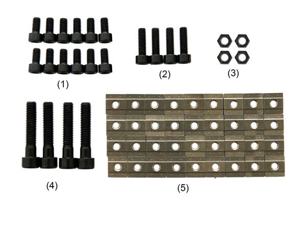
(4) Try Square
-
(5) Caliper 300mm
-
-
-
(1) 2x x-Extrusions
-
(2) 2x y-Extrusions
-
(3) 4x Corner Brackets
-
(4) 4x End Caps
-
(5) 4x Rubber Feet
-
-
-
-
-
-
(3) 4x M6 Self Securing Nuts
-
-
(5) 36x T-Nuts
-
-
-
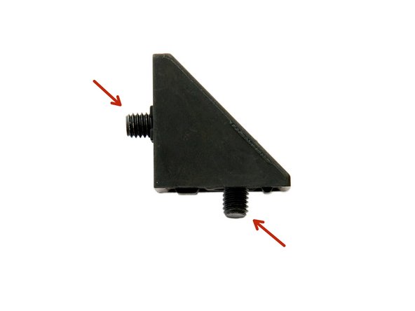
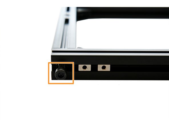
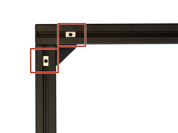
Insert 2x M6x12mm hexagon socket head cap screws into a corner bracket.
-
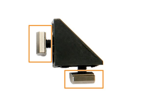
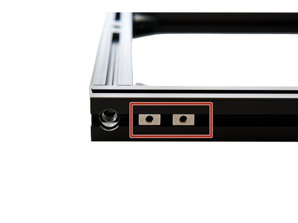
Screw them loosely into the corner bracket and secure it with 2x T-Nuts.
-
Pay attention to the alignment of the T-Nuts (see figure 3)
-
Repeat these steps for the other three corner brackets.
-
-
-
Make sure that the surface, on which you are working, is perfectly flat.
-
Lay out the extrusions as follows:
-
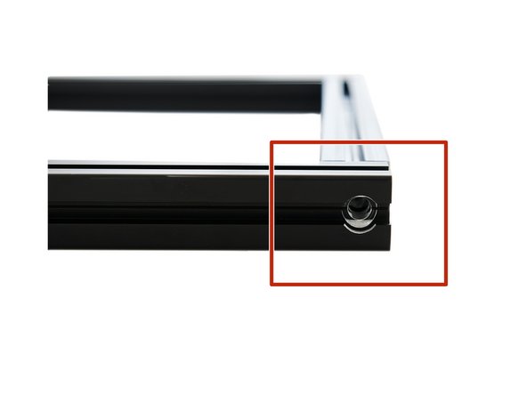
The x-extrusion lies horizontally (viewed from above) and has to be aligned so that the large holes point outward.
-
The y-extrusion lies vertically (as seen from above) and has to be aligned so that the small holes are pointing upwards.
-
Place 2x T-Nuts in each of the upper slots of the y-extrusions.
-
Place 2x T-Nuts in each of the lower slots of the y-extrusions.
-
Check again whether you have inserted two T-Nuts in each of the lower and upper slots of both y-aluminum profiles. If these are missing, the frame must be disassembled again later.
-
-
-
Insert one corner bracket into each of the y-extrusions.
-
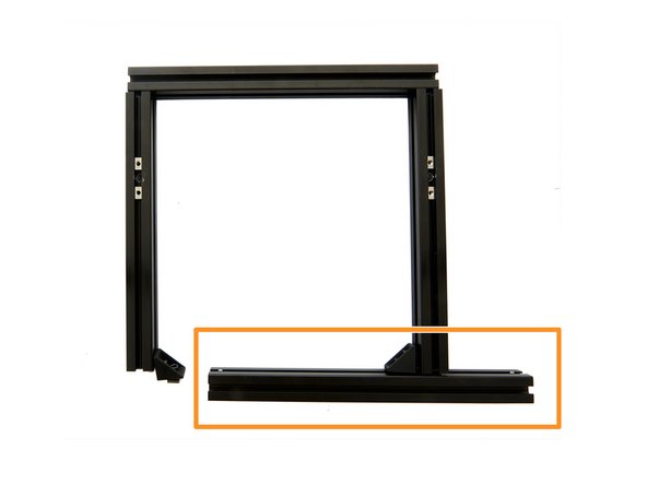
Now, insert the front x-extrusions into the corner brackets.
-
Repeat the last two steps with the rear x-extrusions at the back of the frame.
-
-
-
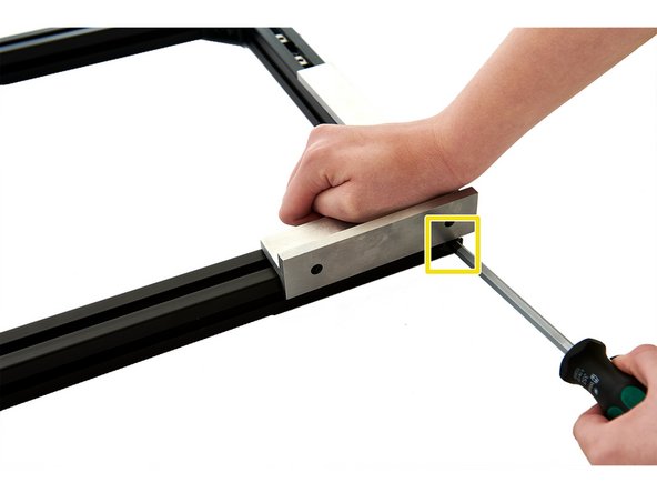
2x T-Nuts must be inserted into the front slot of the x-extrusion.
-
Now insert 2x M8x40mm hexagon socket head cap screws into the front and rear x-extrusion. Tighten the screw slightly.
-
Align two extrusions at a 90° angle using a Try square. While doing so, tighten the M8x40mm hexagon socket head cap screws.
-
Repeat this last step for the other three corners of the frame.
-
The frame should now be flat and it should not wobble at any of its sides.
-
If this is not the case repat the alignement process above.
-
-
-
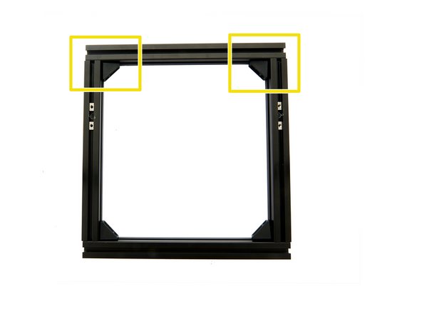
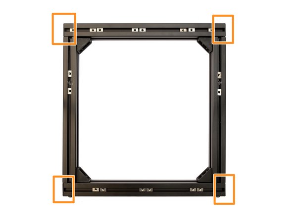
Press the corner brackets into the corners and fasten the 4x M6x12mm hexagon socket head cap screws to the y-extrusions.
-
The 4x M6x12mm hexagon socket head cap screws in the corner brackets at the x-extrusions remain loose.
-
Now loosen the 4x M8x40mm hexagon socket head cap screws by approx. 2-3mm.
-
Each corner bracket should now be flush with the end of the corresponding y-extrusion.
-
If this is not the case repat the alignement process above.
-
-
-
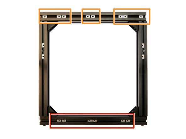
Insert 6x T-Nuts into the upper slot of the front x-extrusion.
-
Insert 8x T-Nuts into the upper slot of the rear x-extrusion.
-
-
-
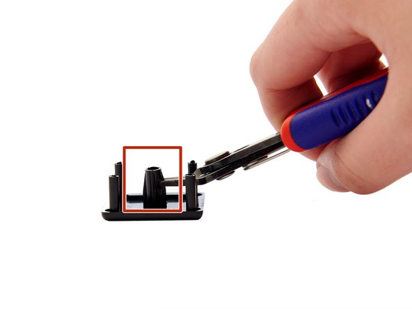
Prepare the 4x end caps by shortening the center part by half (e.g. using a side cutter).
-
Be careful not to shorten the end caps too much, otherwise the end caps will not hold on the extrusions.
-
Now attach the 4x end caps to the ends of the x-extrusions.
-
-
-
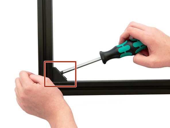
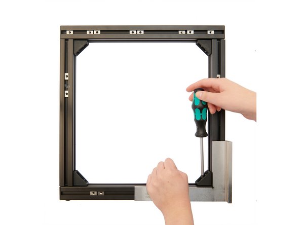
Use a try square to ensure that in one of the four corners the two extrusions are at a 90° angle to each other.
-
Now place the try square on the extrusions and tighten the M6x12mm hexagon socket head cap screws on the x-extrusions in the corner bracket.
-
Make sure that the frame does not twist when you tighten the screws.
-
After repeating this step on the other three corners, check again that all the extrusions are at a 90° angle to each other.
-
If this is not the case, you will have to align the extrusions again.
-
-
-
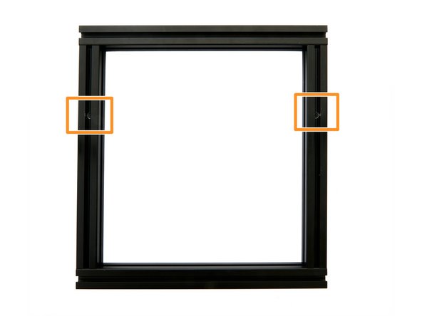
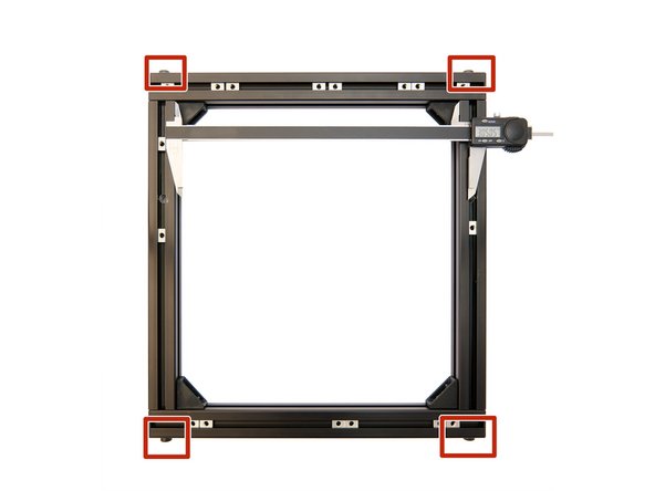
After you have successfully aligned your frame, measure the distance between the two y-profiles with a caliper.
-
To do this, place the calipers at the inner corners of the frame.
-
The distance between the two y-extrusions must be between 305.00 - 305.50mm.
-
The measured values of the front and rear part of the frame, must not have a greater difference than 0.05mm.
-
If the difference in their values is > 0.05mm, you must realign the frame (see Step 10).
-
If the difference in their values is < 0.05mm, tighten the 4x M8x40mm hexagon socket head cap screws in the x-extrusions.
-
If necessary, tighten these four screws with a torque wrench (set to 2.5Nm).
-
To check this, measure the distance between the front and rear y-extrusions again. If these values are < 0.05mm, note the measured values for later and continue with Step 12. If not you have to loosen the 4x M8x40mm hexagon socket head cap screws again and align the frame again (see Step 10).
-
-
-
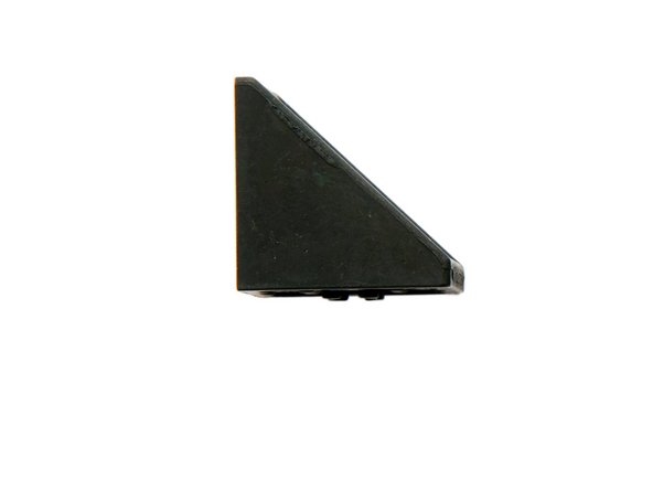
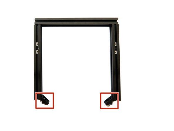
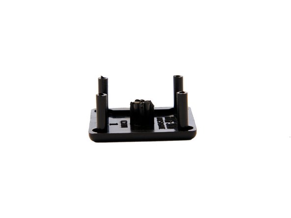
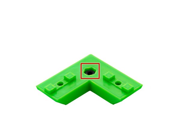
Insert an M6 self securing nut into the L-bracket.
-
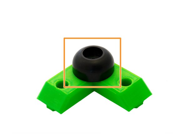
Turn the L-bracket over and place a rubber foot on it.
-
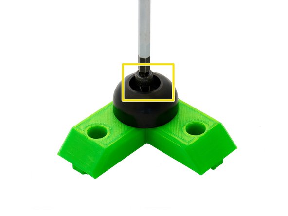
Screw this in place using a M6x20mm hexagon socket head cap screw .
-
Repeat the steps for the other three L-angles.
-
-
-
Turn the frame over.
-
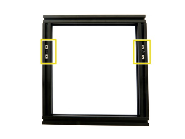
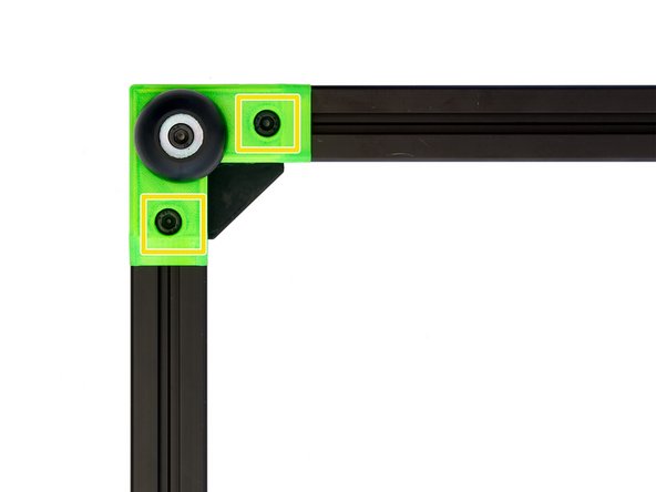
Position one of the already inserted T-Nuts in one of the corners of the frame.
-
Place an L-bracket on the corner (see Fig. 2).
-
Screw it tight with the help of 2x M6x12mm hexagon socket head cap screws .
-
Repeat these steps on the three remaining corners of the frame.
-
Turn the frame over again.
-
-
-
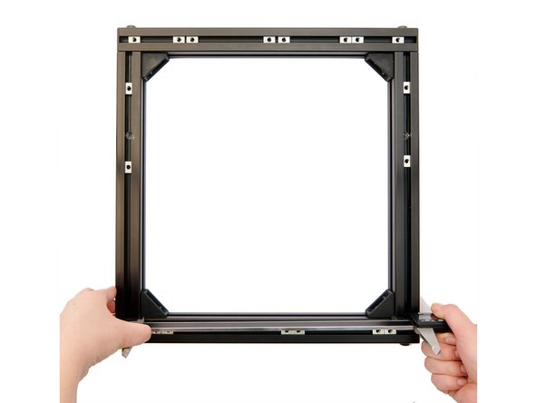
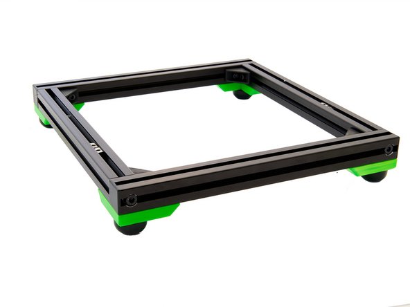
The frame is now completely assembled.
-
Continue with manual 02. Assembly of the y-Axis.
-