-
-
-
-
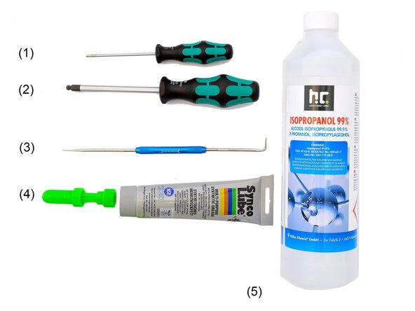
(3) Engineer Scriber
-
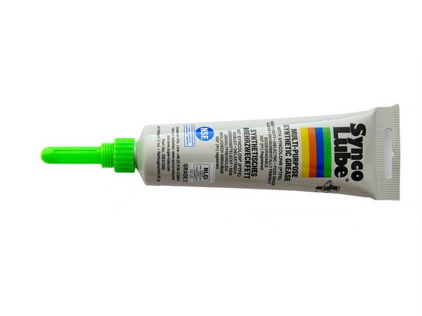
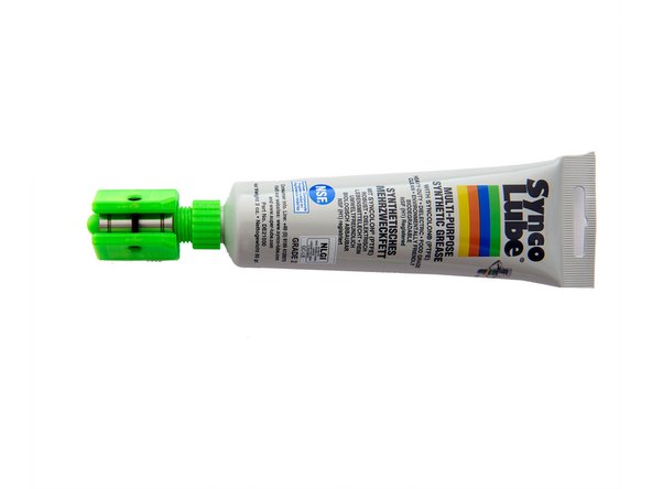
(4) Super Lube + Injector
-
(5) Isopropanol
-
(6) 8mm y-Alignment Tool
-
(7) 10mm y-Alignment Tool
-
-
-
-
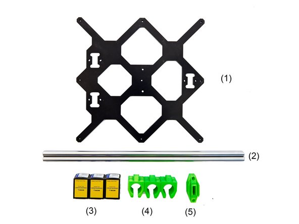
(2) 2x y-Rods 360mm
-
(3) 3x LMU10 Linear Bushing
-
(4) 3x y-Bearing Holder
-
(5) y-Belt Holder
-
-
-
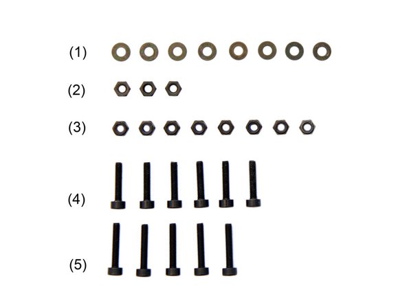
(1) 8x M3 Black Washers
-
(2) 3x M3 Nuts
-
(3) 8x M3 Self-Securing Nuts
-
-
-
-
-
In preparation for later, 3x LMU10 Bushings must be placed in isopropanol for 15min.
-
To save time, you can now already prepare the 3x LUMW10 Bushings and the LMU10 Bushings. You will need these parts later for the construction of the x-axis.
-
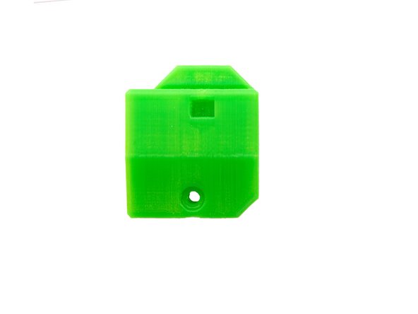
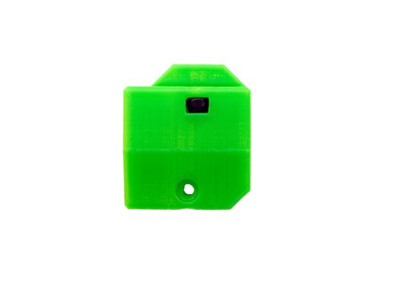
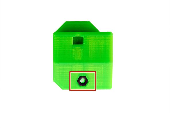
Insert 2x M3 Self-Securing Nuts into the sides of each y-bearing holder.
-
While doing so, check the alignment through the hole on the top of the y-bearing holder.
-
-
-
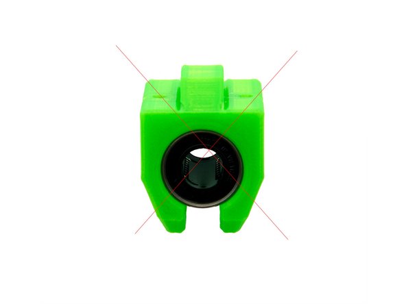
Pay attention to the alignment of the balls. The bushings should be inserted in such a way that the ball guide grooves are positioned at 45° to the vertical line.
-
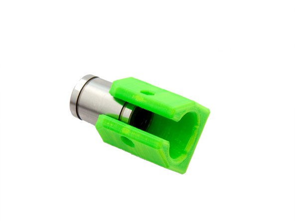
Take one of the LMU10 bushings you have previously soaked in isopropanol, and insert it into the y-bearing holder.
-
Please note that the bushing can only be inserted from one side.
-
-
-
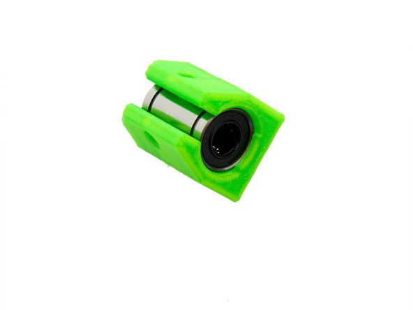
Secure the bushing by inserting an M3 Self-Securing Nut (using an engineer scriber) into one side of the y-bearing holder.
-
They are then lightly tightened with a M3x16mm Hexagon Socket Head Cap Screw.
-
-
-
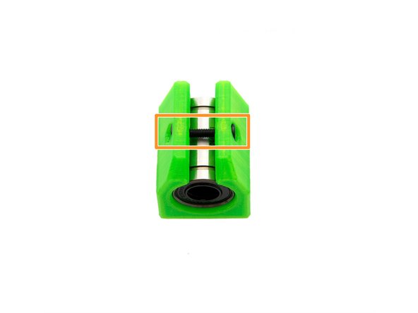
Now open the Super Lube tube and screw the injector onto it.
-
Place the bushing inside the y-bearing holder on the injector. Distribute the Super Lube inside the bushing.
-
The bearing is sufficiently greased when the grease oozes out of both ends of the bushing.
-
Repeat these steps for the other two y-bearing holders.
-
-
-
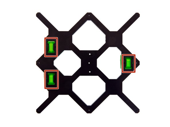
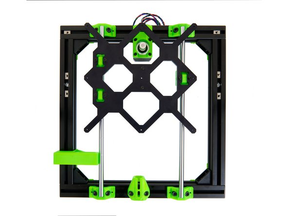
The three assembled bearing holders can now be placed in the holes in the y carriage.
-
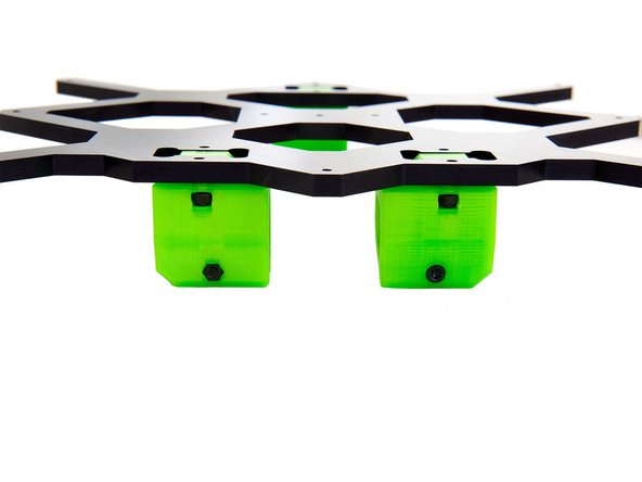
Here, you must pay attention to the alignment of the y-bearing brackets, since on the side on which two y-bearing holders are installed, the flattened sides must face outwards (see Fig. 2).
-
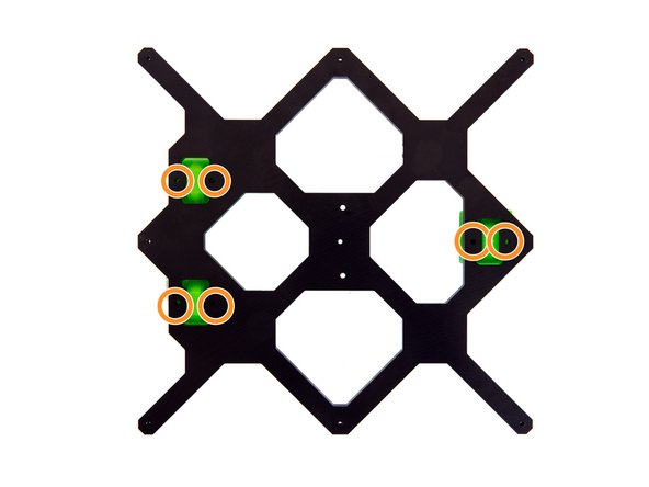
Each y-bearing holder gets loosely attached to the y-carriage with 2x M3 Washers and 2x M3x14mm Hexagon Socket Head Cap Screws.
-
The y-bearing holders should still be easily moveable.
-
-
-
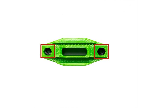
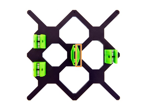
Insert 2x M3 Self-Securing Nuts, (using e.g. an engineer scriber), into the holes of the y-belt holder.
-
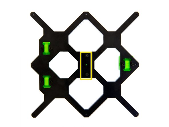
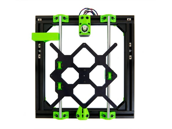
Place the y-belt holder on the y-carriage as shown in Fig. 2.
-
Make sure that the teeth for the belt point to the side with the single bushing.
-
The y-belt holder is attached from the top with 2x M3 Washers and 2x M3x16mm Socket Head Cap Screws.
-
-
-
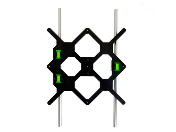
Carefully slide the 2x y-rods through the three bushings and place them on the y-rod holders.
-
Make sure that the side of the y carriage where the two bushings are located, is on the left side of the frame.
-
When the y carriage is correctly aligned, press the rods into the four y-rod holders.
-
-
-
Place the 10mm y-alignment tool at the bottom of the frame's left y-axis and press the rod against it.
-
Then place the alignment tool on top of the left y-axis and press the rod against it here as well.
-
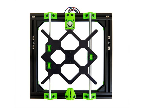
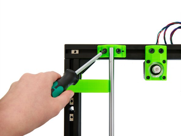
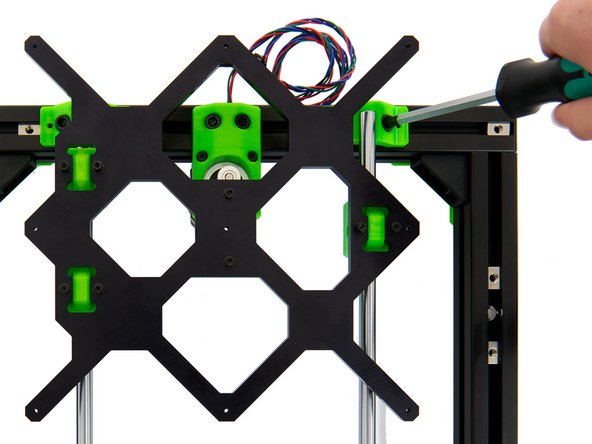
Once you have correctly aligned the rod, fasten the 4x M6x12mm Socket Head Cap Screws inside the y-rodholder at (1) the left front and (2) the left rear.
-
-
-
Then move the y carriage to the far front and fasten the 2x M6x12mm Socket Head Cap Screws in the y-rod holder on the right front.
-
Move the y-carriage to the far rear and fasten the 2x M6x12mm Socket Head Cap Screws in the y-rod holder at the right rear.
-
-
-
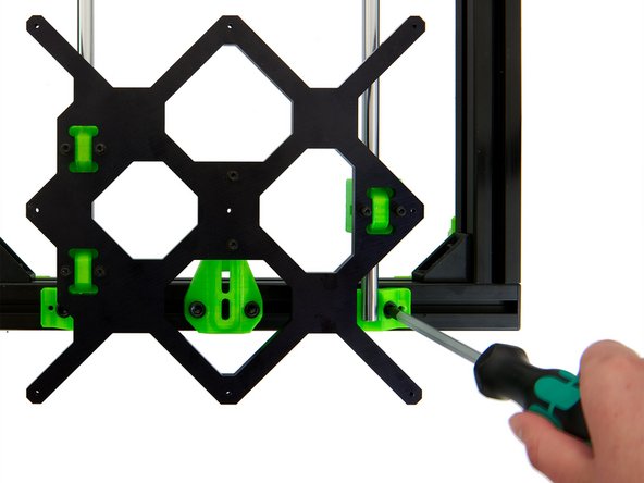
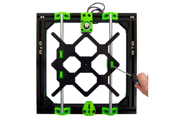
Move the y-carriage back and forth while gradually tightening the 6x M3x14mm Socket Head Cap Screws on the y-bearing holders.
-
Do not fully fasten the screws immediately. Fasten each screw with only half a turn for the time being.
-
Keep moving the carriage back and forth to make sure it can move freely.
-
If the y-carriage runs a little out of round, both loosening and tightening the screws on the y-bearing holders several times and realigning the rods can help.
-
-
-
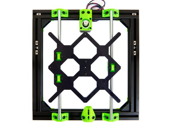
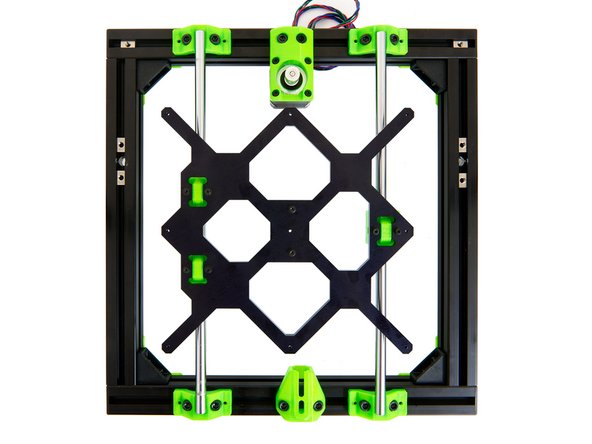
The heat bed carriage for MK52 is now completely installed.
-
Continue with instructions 04. Installing the y-Belt.
-