Introduction
Klipper supports the so-called. Input shaping. As a result, "ringing" or “ ghosting ” can be significantly reduced (especially at high printing speeds). We use an inexpensive acceleration sensor (accelerometer) of type ADXL345 for the X and Y axes to measure the resonances. This tutorial is primarily about the practical implementation. If you want to know more about the topic, you will here found.
-
-
An ADXL345 module (e.g. available from amazon, cost approx. 2.00 to 5.00 euros)
-
There are different versions of these modules. The order of the pin assignment can therefore differ from the photo.
-
A printed holder for the Y axis, stl download from here. A nut M3 and a screw M3x12.
-
Six dupont cables female / female, minimum length 40cm
-
Possibly. a soldering iron and some solder.
-
-
-
The connector strip is not yet soldered on most ADXL345 modules. Solder them onto the top of the board and pinch protruding tips on the bottom with a small pair of pliers.
-
Disconnect the printer and Raspberry Pi from the power.
-
Connect the Raspberry Pi and the ADXL345 module to the Dupont cables as shown in the sketch and photo.
-
Check the cabling! If the cabling is faulty, the pi or accelerometer can be damaged.
-
-
-
Go to "Safe number" and make a 1: 1 copy of the MicroSD, which is located in the Raspberry Pi. This works e.g. with the tool Win32DiskImager without problems under Windows.
-
We also need the tools under Windows Putty and WinSCP, that we already know from the other tutorials.
-
Reconnect the pi and printer and boot with the backup copy. We first log in to our clipper system via Putty via SSH connection.
-
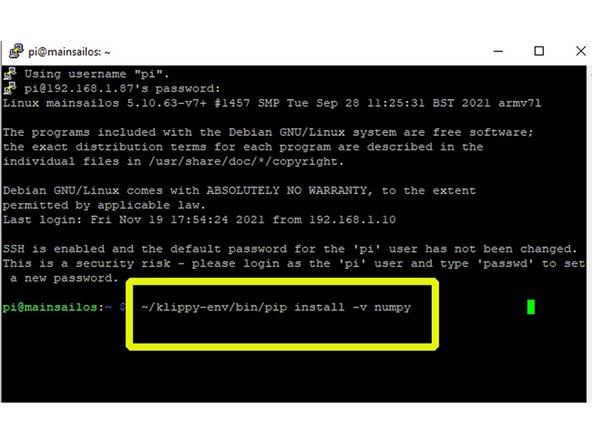
First, the NumPy Python program library must be installed. We give the command ~ / klippy-env / bin / pip install -v numpy and confirm with Enter. The installation can take up to 20 minutes.
-
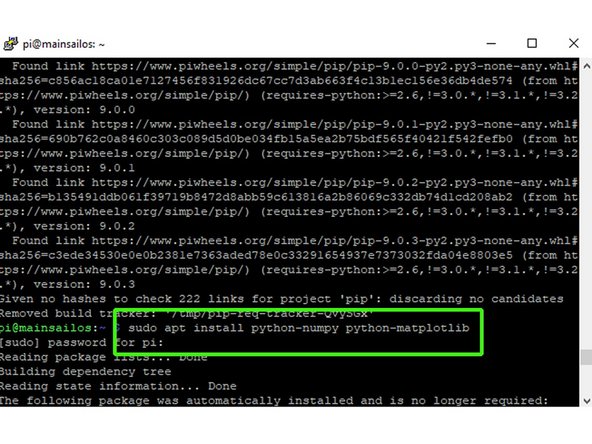
After that we give sudo apt install python-numpy python-matplotlib and confirm again with Enter. Now further, program-related dependencies are installed.
-
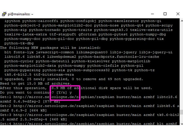
We answer the following query with "Yes".
-
-
-
For communication between the accelerometer and the pi, we have to activate the pi's SPI interface.
-
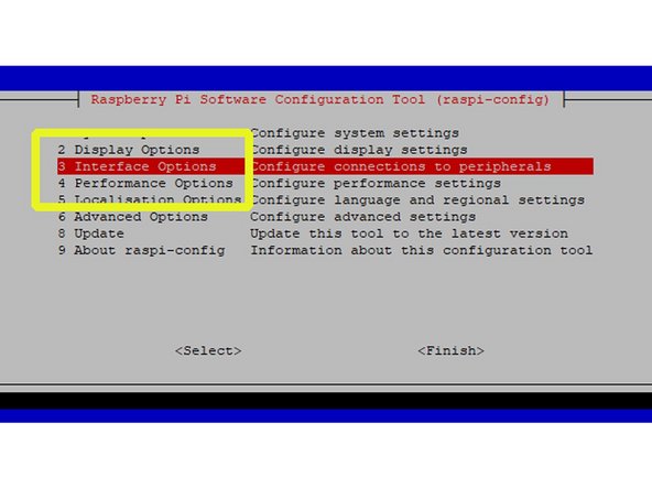
We first give in Putty sudo raspi-config enter, confirm with Enter and then enter our password.
-
In the configuration tool we first select point 3 Interface options.
-
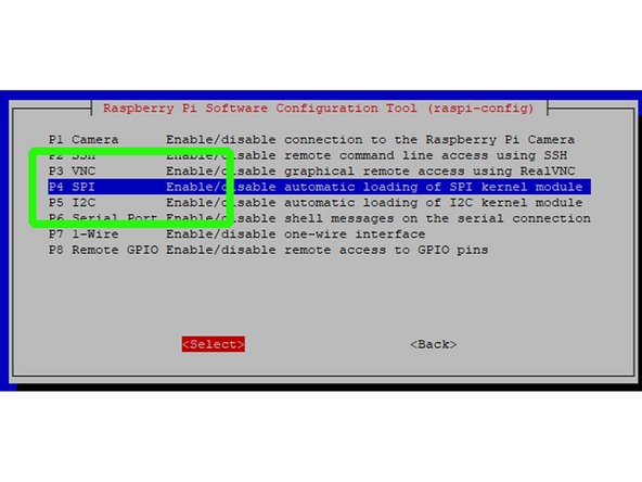
Another configuration window opens and we choose P4 SPI. We go to "Select" and save the change.
-
-
-
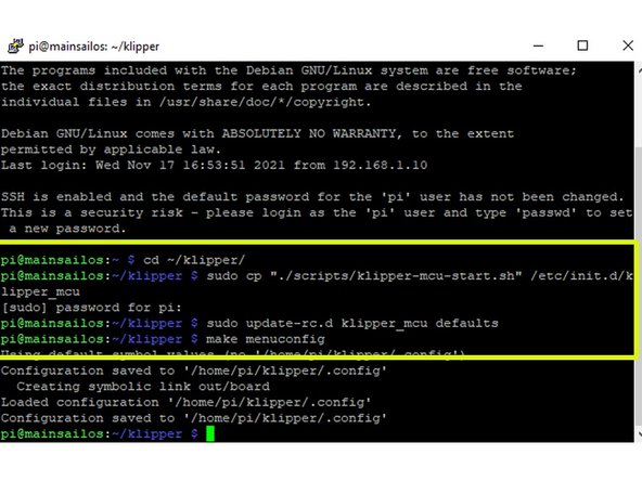
We log in again about Putty and give cd ~ / clipper/ a plus enter. After that sudo cp "./scripts/klipper-mcu-start.sh" /etc/init.d/klipper_mcu plus enter and password confirmation followed by sudo update-rc.d klipper_mcu defaults plus enter and make menuconfig plus enter.
-
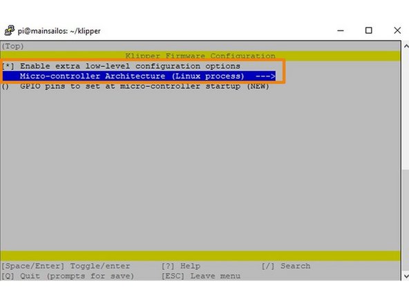
A configuration window opens where we Enable extra low level and MicroController Architecture (Linux process) activate. We save via "Quit".
-
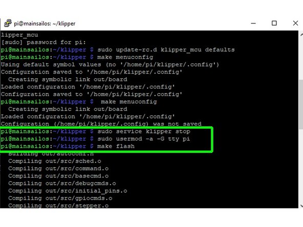
We give then sudo service clipper stop plus enter, followed by sudo usermod -a -G tty pi plus enter . With make flash plus Enter, the virtual printer is created. About sudo service clipper start plus Enter, Klipper is restarted.
-
-
-
Changes to the configuration are required for measurements with the ADXL345. These are taken back after the measurement.
-
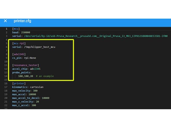
We now open in Mainsail under "Machine" printer.cfg and enter the following lines: [mcu rpi] serial: / tmp / klipper_host_mcu [adxl345] cs_pin: rpi: None [resonance_tester] accel_chip: adxl345 probe_points: 100,100,20 # an example
-
Orientate yourself when formatting on the screenshot shown!
-
Then put max_accel and max_accel_to_decel on 10000 up.
-
After the measurement, make sure to reset these values to the normal values or use the original SD again.
-
Save the changes.
-
-
-
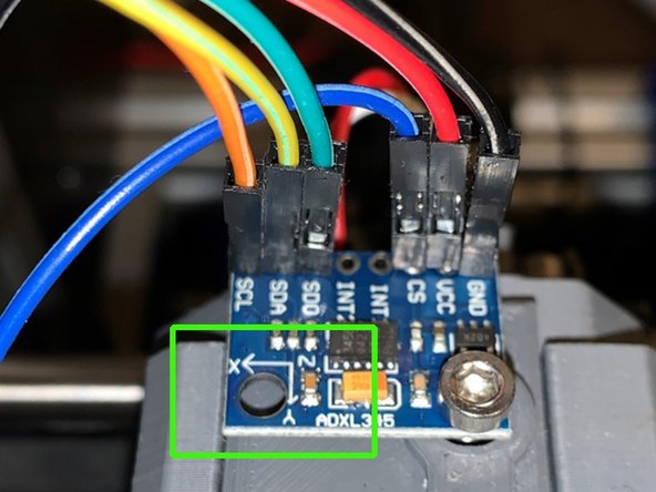
A bracket for the ADXL345 module is not absolutely necessary for the measurement on the X axis. It can be fixed on the lid of the filament sensor with the M3 screw.
-
Possibly. a slightly longer M3 screw must be used.
-
Make sure that the X axis marking on the accelerometer is actually parallel to the X axis. The module must be well fixed!
-
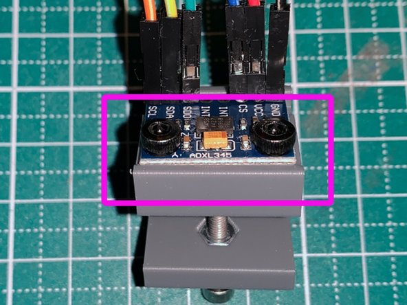
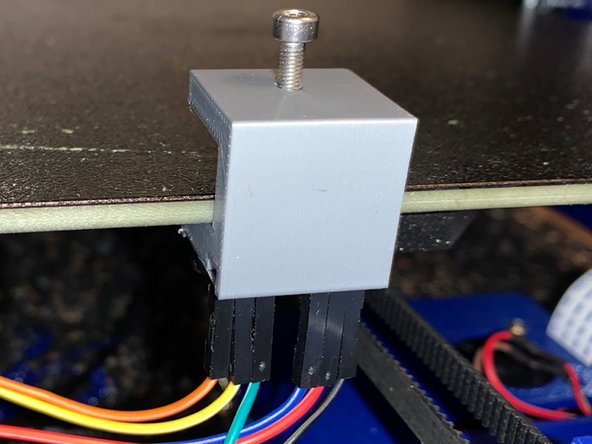
We use the printed bracket for the Y axis. First fix the module with two short M3 screws. For the second measurement, clamp the holder with module on the front of the pressure bed (see. Photo).
-
-
-
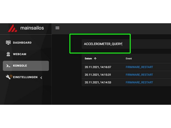
First we test the function of the ADXL345. To do this, we open mainsail, enter in the console ACCELEROMETER_QUERY and go up SEND. Three values should now be displayed. If this is not the case, check the cabling again.
-
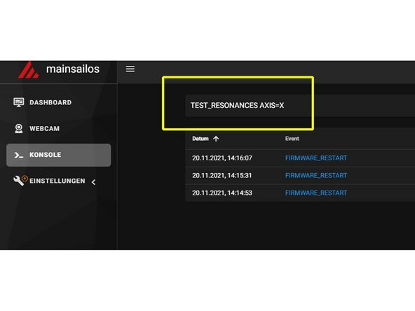
If the test was successful, we can use it TEST_RESONANCES AXIS = X start our measurement for the X axis.
-
The measurement takes a few minutes and it gets quite loud at times. Don't leave the printer unattended!!
-
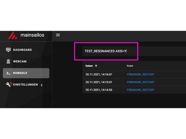
When the measurement of the X axis is finished, the ADXL345 module - as previously described - is mounted on the heating bed. We start the second measurement with TEST_RESONANCES AXIS = Y
-
-
-
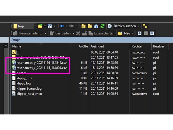
We now open the Win SCP tool and navigate to the folder tmp in the main directory. There should now be two csv files.
-
We copy these two files to our hard drive with WinSCP for safety reasons, because the folder tmp is deleted during the shutdown of the PI.
-
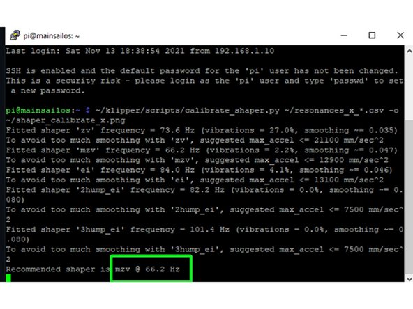
We go back to the putty terminal and enter the following line: ~ /klipper/scripts/calibrate_shaper.py ~ /resonances_x_*.csv -o ~ /shaper_calibrate_x.png The script now performs a few calculations and ends up with a shaper type and frequency.
-
Klipper supports several shapers. We usually recommend MZV or EI. Other shapers work more aggressively. Although more ringing is eliminated, edges are blurred or slightly printed.
-
We proceed analogously for the Y axis. The input is: ~ /klipper/scripts/calibrate_shaper.py ~ /resonances_y_*.csv -o ~ /shaper_calibrate_y.png
-
-
-
If we now have the folder again in WinSCP tmp open, two graphics in the format * .png should have been added there.
-
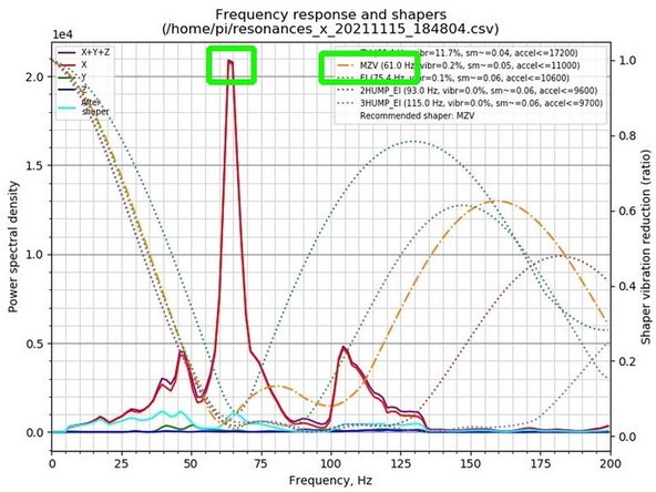
The graphics can be opened with Windows tools. The graphic evaluation for "X" is shown in the screenshot shown". The recommended shaper MZV correlates with the peak of the X curve.
-
The MZV shaper in the graphic shown differs somewhat from the shaper recommendation from step 9 (66.2Hz vs. 61.0Hz) because this is a different measurement with a different setup.
-
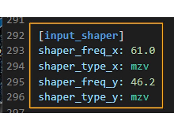
We open in Mainsail under "Machine" printer.cfg and add the proposed shapers and frequencies [input_shaper] in our configuration and save it.
-
We can now switch off the printer and the Pi, remove the ADXL345 module from the heating bed and remove the Dupont cables from the Pi. If something changes in the setup of the printer or the printer is moved, a new measurement should be made.
-
-
-
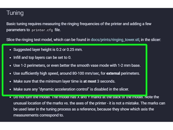
Under https://www.klipper3d.org/prints/ringing... a test model for input shaper tuning can be downloaded. Note the slicer settings (s. Screenshot) and deactivate PA before printing by entering SET_PRESSURE_ADVANCE ADVANCE = 0 in the mainsail console.
-
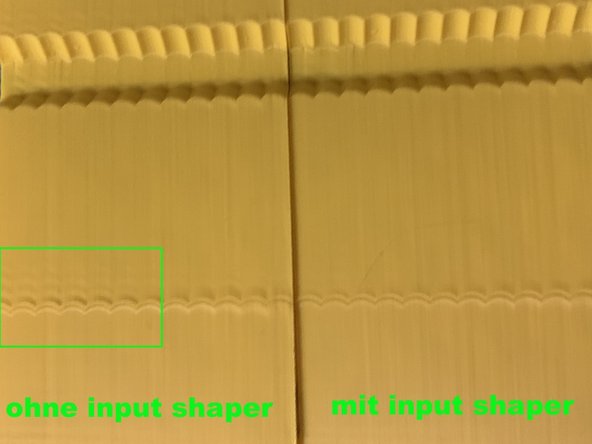
The ringing is clearly visible on the left model (printed without shaper), on the right (with shaper) it looks much better in this regard :-)
-
-
-
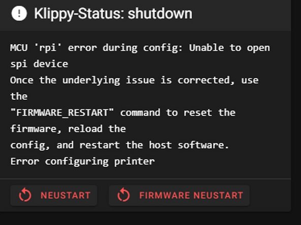
Sometimes the error message shown comes. There is often a conflict here if e.g. Access the SPI interface of the touchscreen driver. Solution: We open via sudo nano /boot/config.txt the screen configuration, set in front dtoverlay a pound sign and save. After a reboot, the bug should be fixed.
-
We do not need the display for the measurements. After the measurement has been carried out dtoverlay be reactivated.
-


![We now open in Mainsail under "Machine" printer.cfg and enter the following lines: [mcu rpi] serial: / tmp / klipper_host_mcu [adxl345] cs_pin: rpi: None [resonance_tester] accel_chip: adxl345 probe_points: 100,100,20 # an example](https://d3t0tbmlie281e.cloudfront.net/igi/caribou3d/LU2lqLtBhUpSDhNJ.medium)
