Introduction
This guide describes the installation of the Bondtech LGX with Copperhead hot end on the Caribou 10mm version. Please note that you will need different firmware on Caribou MK3s and different configuration files on CaribouDuet as well.
-
-
-
(2) Bondtech LGX™ For Flexibles Set (heatsink, holder for Copperhead, heat break, Copperhead, nozzle)
-
(3) LGX™ Short Plastic Set for FF on Prusa (filament sensor holder, extruder holder, fan shroud, PINDA holder)
-
(4) x-carriage, x-carriage back top and bottom, belt holder, x-cable holder
-
-
-
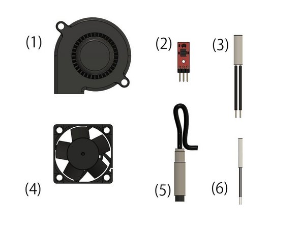
(1) Radial fan
-
-
(3) Heater
-
(4) Sunon fan
-
(5) PINDA2 / SuperPINDA
-
(6) Thermistor
-
For the installation you will also need one sachet of boron nitride paste.
-
-
-
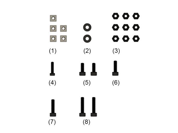
(1) 5x M3 square nuts
-
(2) 2x M3 washers
-
(3) 9x M3 nuts
-
(4) M2.5x10mm low profile hexagon socket head cap screw
-
-
-
-
-
-
-
-
-
-
-
-
(6) 2x M3x15mm hex drive flat head screws (silver)
-
(7) 2x M3x28mm hex drive flat head screws
-
-
-
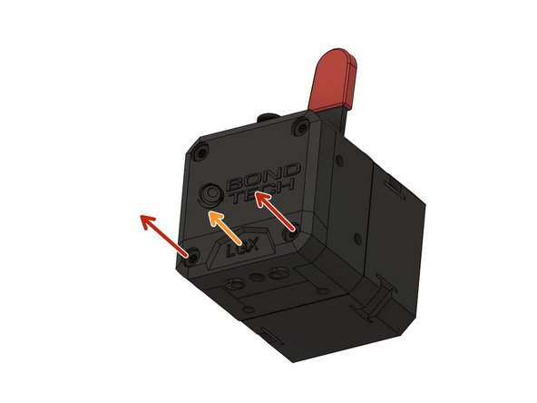
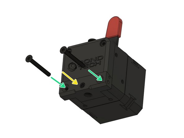
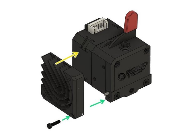
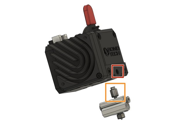
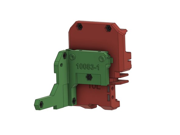
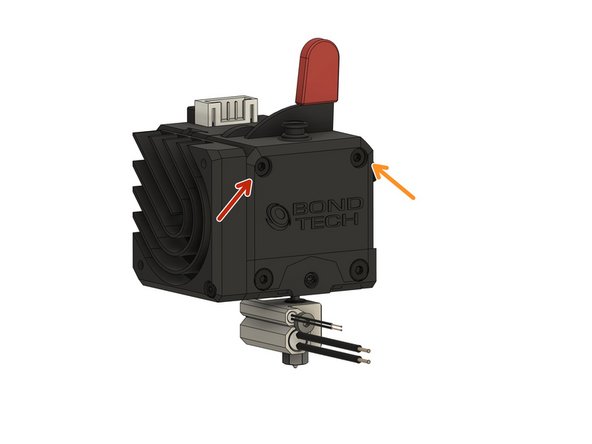
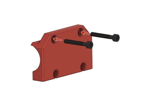
The LGX comes with the mount for the Mosquito installed. You have to replace it with the mount for the Copperhead.
-
Unscrew 2x M3x28mm hexagon socket head cap screws.
-
Remove the mount for the Mosquito.
-
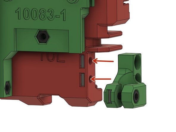
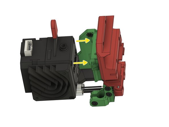
Bring the Copperhead mount into position.
-
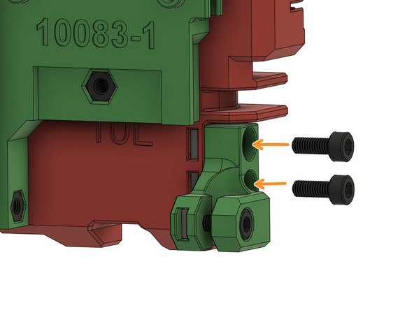
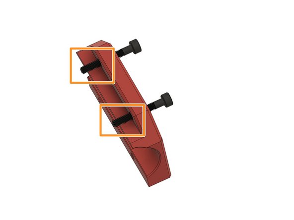
Use 2x M3x28mm hexagon socket head cap screws to fasten the mount slightly.
-
Do not tighten the M3x28mm hexagon socket head cap screws yet.
-
-
-
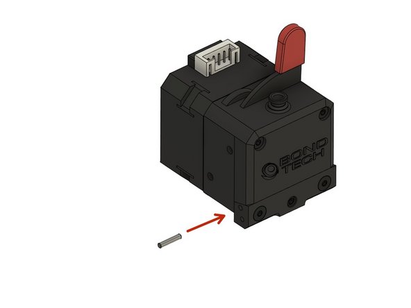
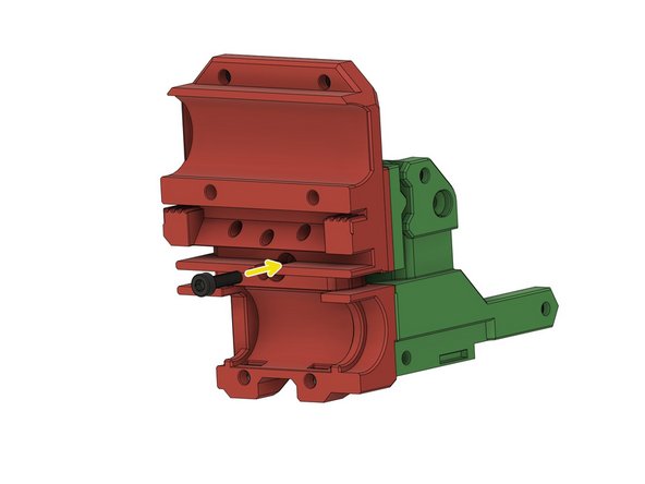
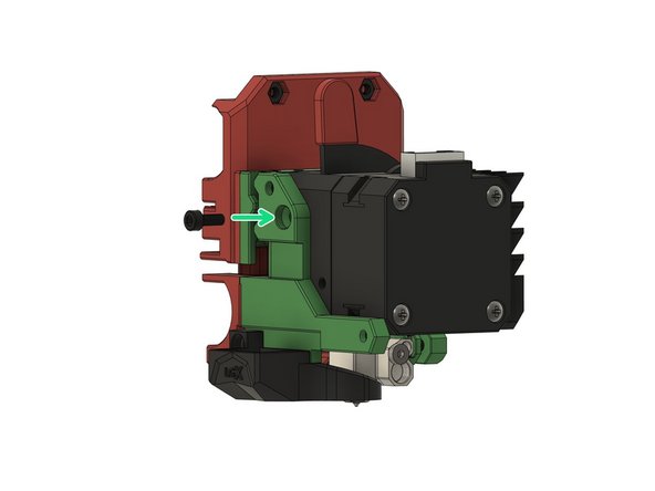
Before inserting the pin, apply thermal paste onto the entire surface that connects the heat sink and the holder for the Copperhead.
-
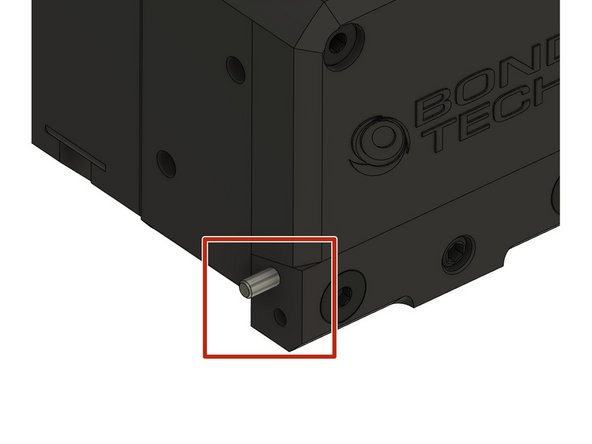
Insert the 10mm dowel pin on the left side (seen from the front) into the Copperhead holder.
-
Align the heatsink as shown. Pay attention to the holes on the back of the heatsink.
-
Use a M2.5x10mm low profile hexagon socket head cap screw to fasten the heatsink.
-
-
-
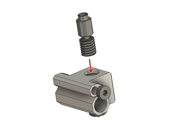
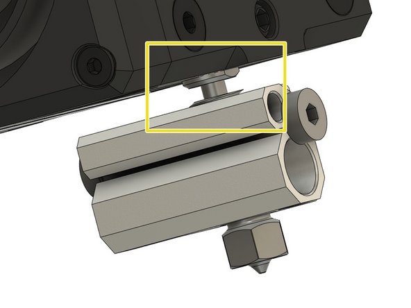
Screw the heat break into the Copperhead heat block.
-
Screw the heat break almost entirely in.
-
Make sure the flat side of the upper part is in the position shown.
-
Screw the nozzle into the Copperhead. Fasten lightly so that the heat break is still able to rotate.
-
-
-
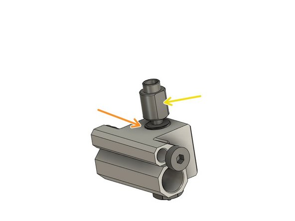
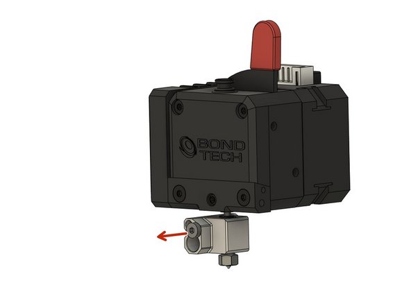
Loosen the grub screw of the Copperhead holder.
-
Apply Boron nitride paste to the upper part of the heat break.
-
Align the Copperhead so that the heat break's flat side is front facing.
-
Insert the heat break fully into to the heat sink. If the heat break stands out more than about a millimeter, slightly loosen the M3x28 countersunk screw.
-
Fasten the grub screw.
-
Fasten the 2x M3x28mm hexagon socket head cap screws.
-
-
-
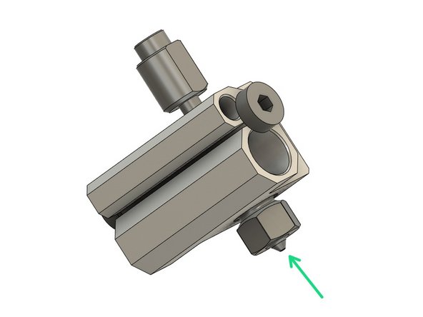
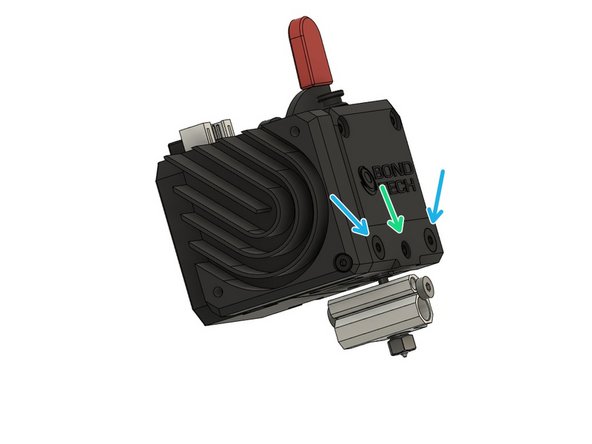
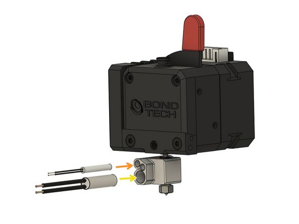
Remove the M2.5x5mm low profile hexagon socket head cap screw on the front of the Copperhead.
-
Apply boron nitride paste to the heater cartridge and the thermistor cartridge.
-
Insert the thermistor cartridge into the upper hole.
-
Insert the thermistor cartridge into the lower hole.
-
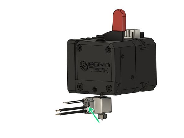
Fasten the M2.5x5mm hexagon socket head cap screws to secure the cartridges.
-
-
-
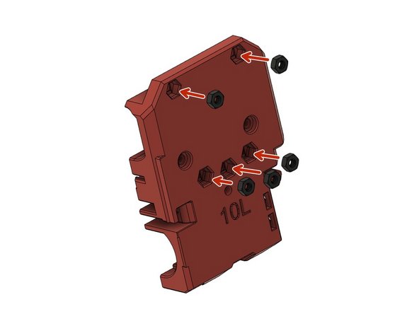
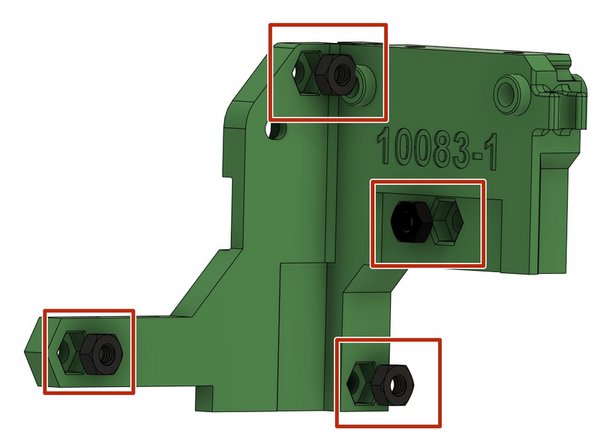
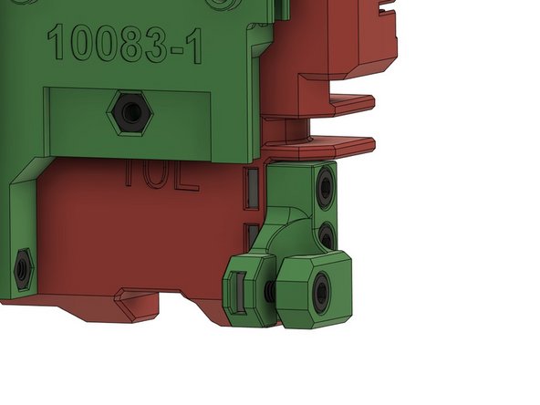
Insert 5x M3 nut.
-
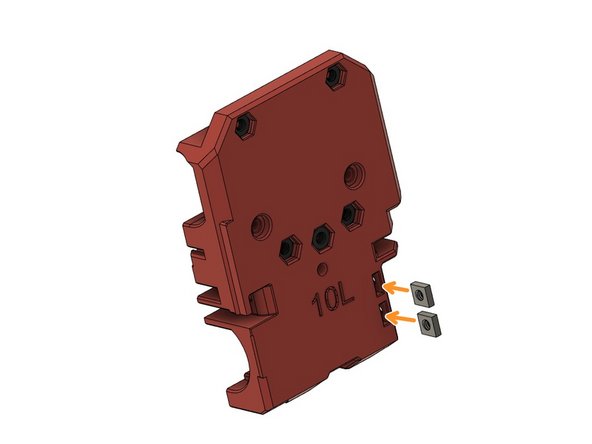
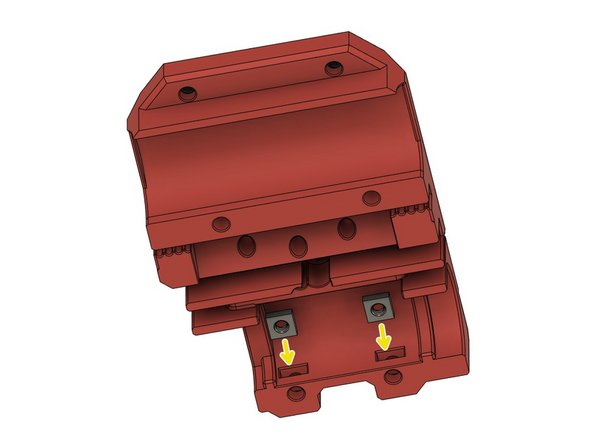
Insert 2x M3 square nut.
-
Insert 2x M3 square nut.
-
-
-
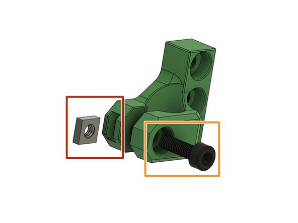
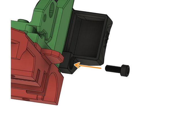
Insert a M3 square nut.
-
Insert a M3x10mm hexagon socket head cap screw and fasten it loosely.
-
-
-
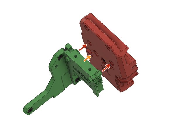
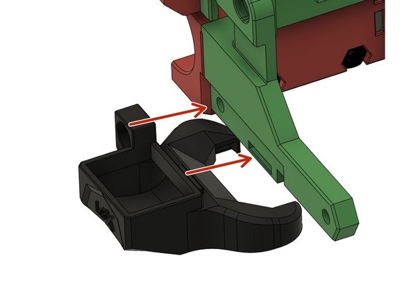
Align the holes of the holder and the x-carriage.
-
Attach the holder to the x-carriage.
-
Screw the plastic parts together with M3x12mm hexagon socket head cap screw.
-
-
-
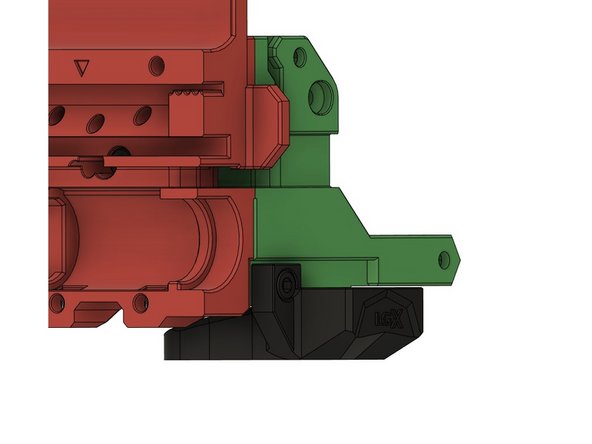
Align the holes of the PINDA holder with the holes of the x-carriage.
-
Use 2x M3x10mm hexagon socket head cap screws to fasten the holder.
-
-
-
Align the hole of the shroud and the extruder holder and make sure the tongue and groove are aligned as well.
-
Fasten the fan shroud with M3x8mm hexagon socket head cap screw.
-
-
-
Remove the M3x10mm hexagon socket head cap screw.
-
Remove the M3x28mm hexagon socket head cap screw.
-
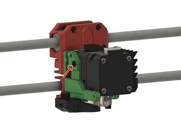
Align the upper holes on the front of the extruder with the holes of the holder. Firmly press the extruder onto the holder.
-
Secure the extruder in the holder with a M3x8mm hexagon socket head cap screw.
-
-
-
Loosen the M3x10mm hexagon socket head cap screw.
-
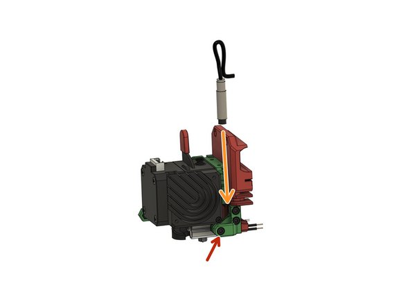
Insert the PINDA / SuperPINDA probe into the hole.
-
Align the tip of the nozzle with the tip of the probe.
-
Please note that this is not the position for printing. We'll adjust the position later.
-
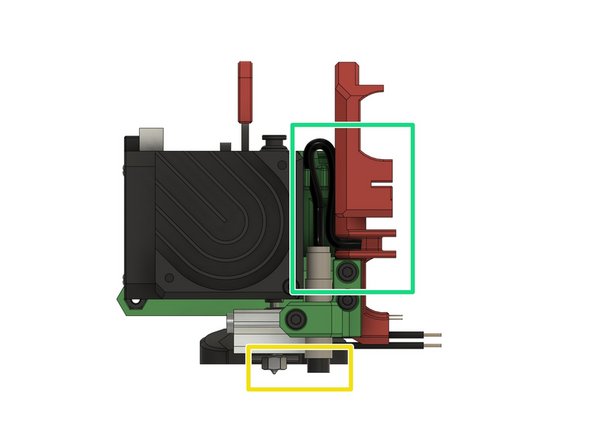
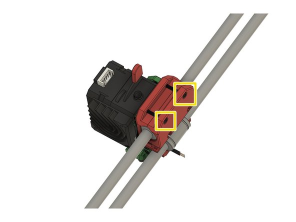
Route both the cable of the extruder fan and the cable of the probe through the chanel. Stick to the path shown in the picture.
-
-
-
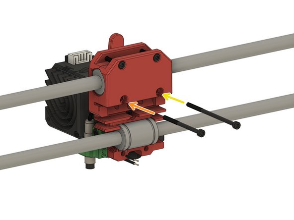
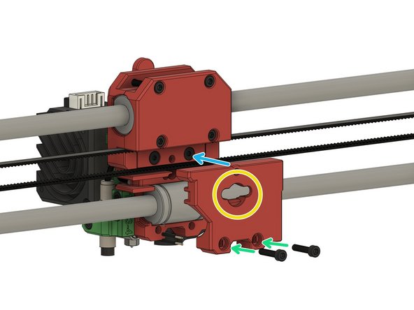
Insert 2x M3x22mm hexagon socket head cap screws into the upper holes of the holder.
-
Only screw them half the way in for now.
-
-
-
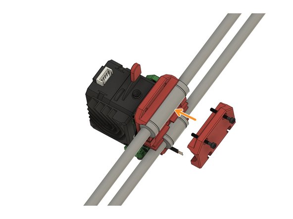
Align the bearings with the x-carriage back.
-
Bring the top holder back in position.
-
Fasten the 2x M3x22mm hexagon socket head cap screws.
-
Do not overtighten the screws.
-
-
-
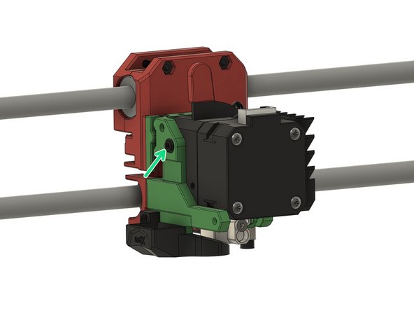
Slitghly loosen the M3x8mm hexagon socket head cap screw on the side.
-
Use a M3x45mm hexagon socket head cap screw and...
-
... a M3x60mm hexagon socket head cap screw to fasten the back holder to the extruder.
-
Fasten the M3x8mm hexagon socket head cap screw once more.
-
-
-
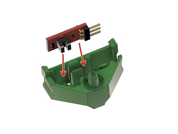
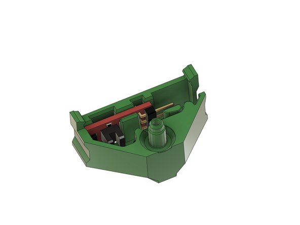
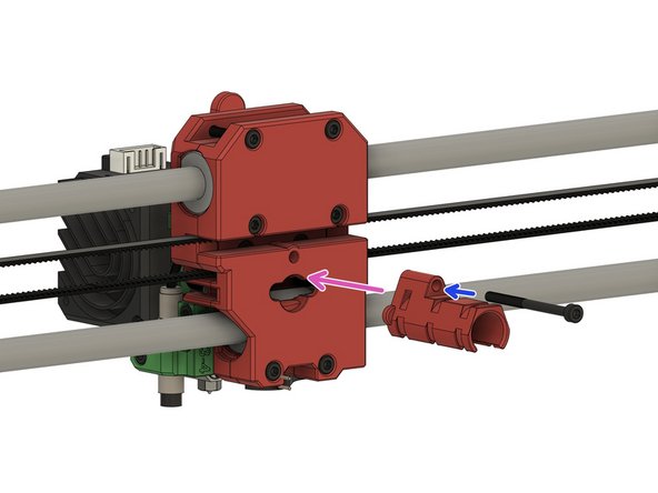
Insert the filament sensor into the housing.
-
-
-
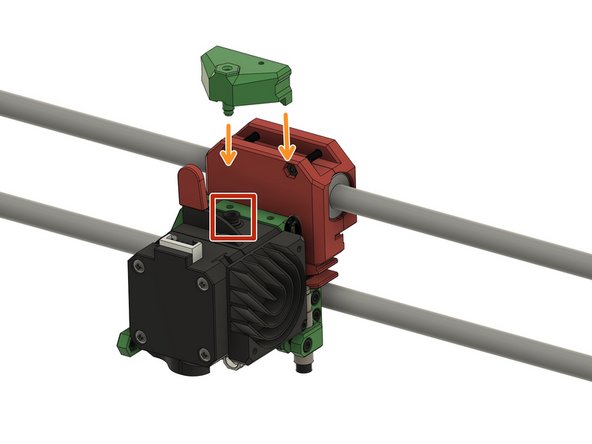
Remove (pull out) the bowden connector.
-
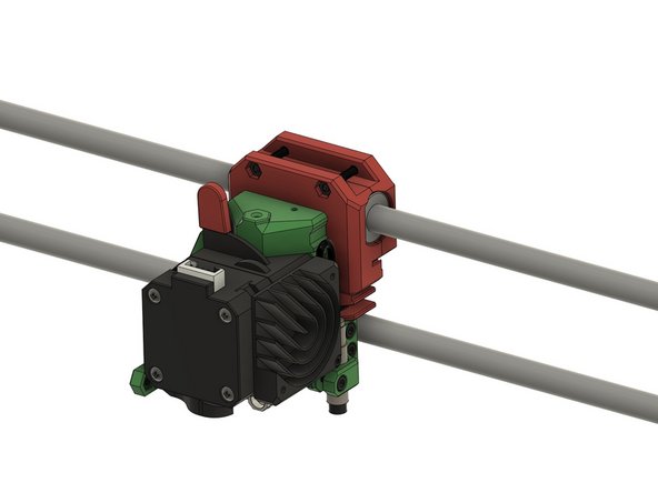
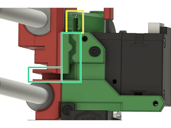
Align the filament sensor housing and clip it into the extruder holder.
-
Plug in the cable of the sensor.
-
Route the cable through highlighted cable channel.
-
-
-
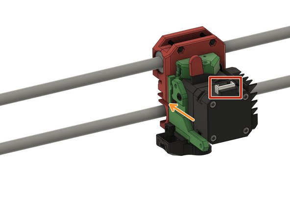
Plug the connector of the motor cable into the extruder motor.
-
Route the cable through the cable channel.
-
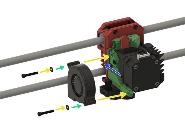
Use 2x M3 washers and...
-
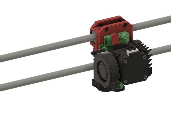
...2x M3x20mm hexagon socket head cap screws to fasten the radial fan to the extruder holder.
-
Route the cable through the cable channel behind the radial fan.
-
-
-
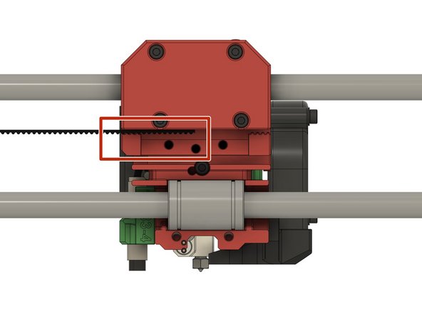
Insert one end of the belt on side into the x-carriage. It should be inserted half way into the x-carriage.
-
Route the belt through the x-idler and the x-motor holder (not shown here).
-
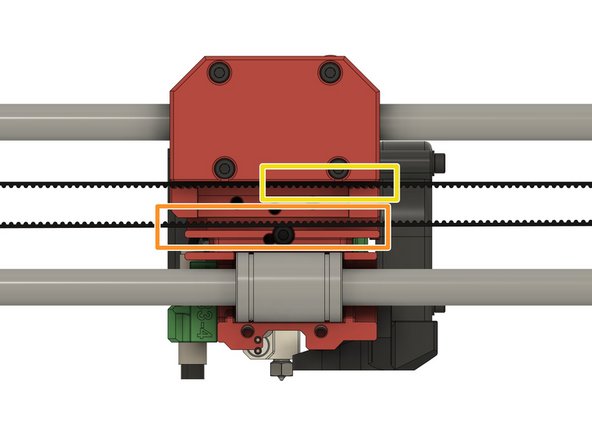
The belt must run through the lower channel of the x-carriage.
-
Cut the belt so that you can insert the other end of the belt into the x-carriage. It should touch the other end of the belt.
-
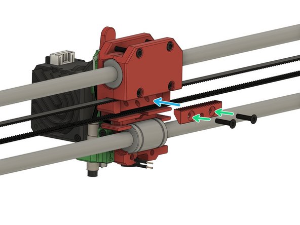
Use 2x M3x14mm hex drive flat head screws to...
-
...fasten the belt holder into the x-carriage.
-
-
-
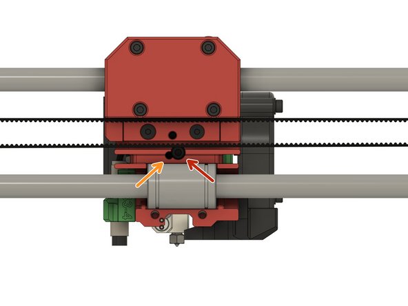
Loosen the M3x12mm hexagon socket head cap screw and take it out.
-
Insert the 2.85mm nylon filament into the hole next to the screw hole.
-
Fasten the M3x12mm hexagon socket head cap screw to secure the nylon filament in position.
-
Route the cables for the fans, the PINDA, the filament sensor cable, and the extruder motor through the hole.
-
Use 2x M3x14mm hexagon socket head cap screws to...
-
...fasten the carriage's back bottom part to the x-carriage.
-
Use a M3x40mm hexagon socket head cap screw to...
-
...fasten the cable holder to the x-carriage.
-