
-
-
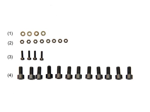
(1) Stepper Motor
-
-
(3) 4x y-Rodholder Bottom
-
(4) y-Motorholder
-
(5) y-Belt Tensioner
-
-
-
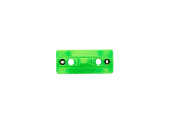
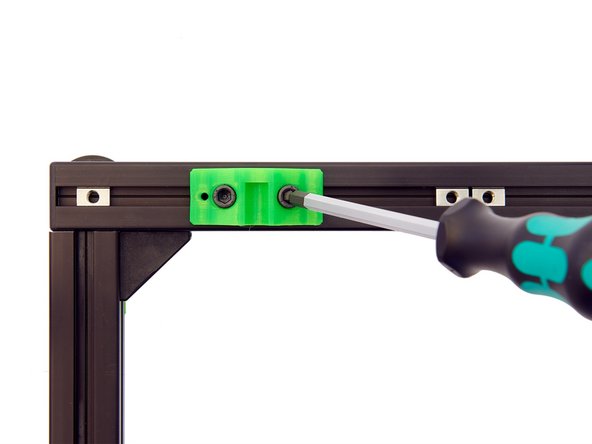
Using an Engineer Scriber, insert 2x M3 Self-Securing Nuts into each of the y-bar holders.
-
Alternatively, you can tighten the M3 Self-Securing Nuts with an M3 Screw from the other side.
-
-
-
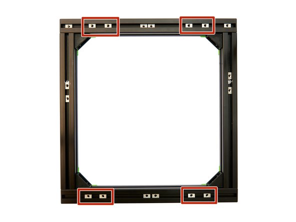
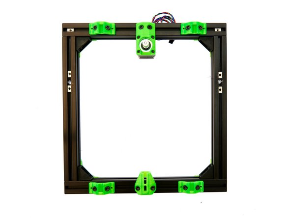
Align the T-Nuts and the frame as shown in figure 1.
-
Now, place the four y-rodholders on the frame (see figure 3), assigning each hole to a T-Nut.
-
For the x-axes, make sure that there are 2x T-Nuts between the two y-rodholders.
-
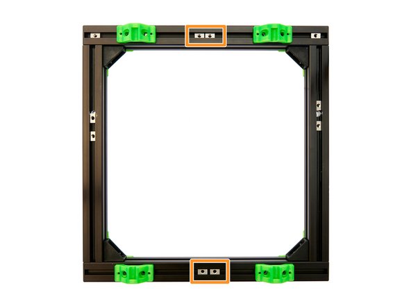
The y-rodholders are now screwed on using 8x M6x12mm Hexagon Socket Head Cap Screws.
-
These screws are initially only loosely tightened, as the y-rodholders need to remain movable.
-
-
-
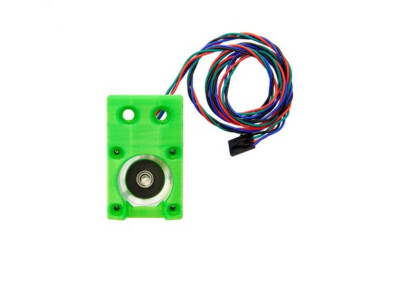
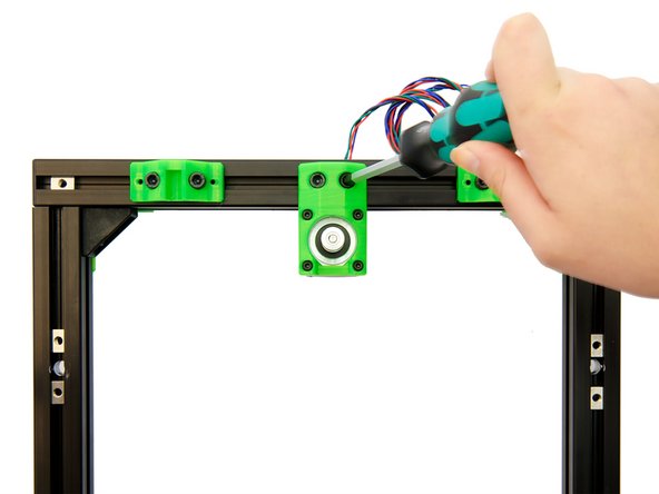
Place the y-motorholder on to the stepper motor.
-
Make sure the cables are leading to the holes for the M6 screws.
-
Then, attach the motor to the y-motorholder. Use the 4x M3 Washers and the 4x M3x10mm Hexagon Socket Head Cap Screws to fasten it.
-
-
-
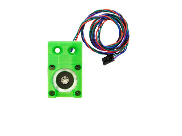
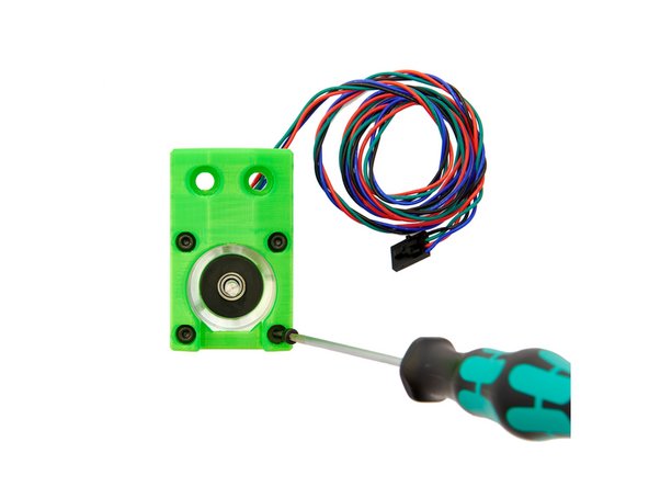
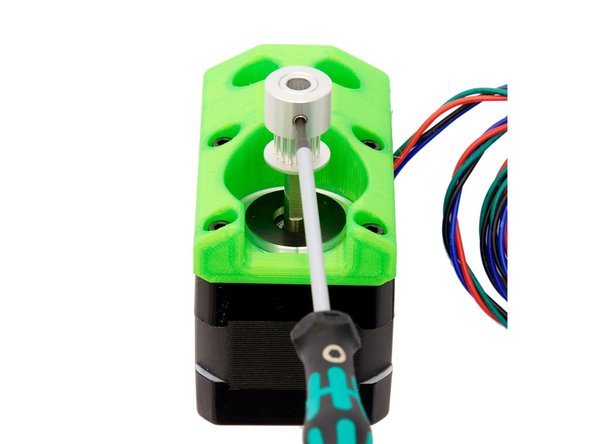
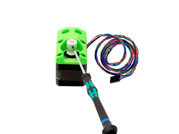
Slide the GT3 pulley onto the motor shaft of the stepper motor.
-
The GT3 pulley has two grub screws. Ensure that one of these screws is aligned with the flat surface of the shaft. Then, tighten both grub screws.
-
To avoid friction, leave a small gap between the pulley and the motor surface.
-
-
-
Attach the assembled y-motorholders to the 2x T-Nuts between the two y-rodholders in the rear x-axis. Use 2x M6x12mm Hexagon Socket Head Cap Screws for this.
-
-
-
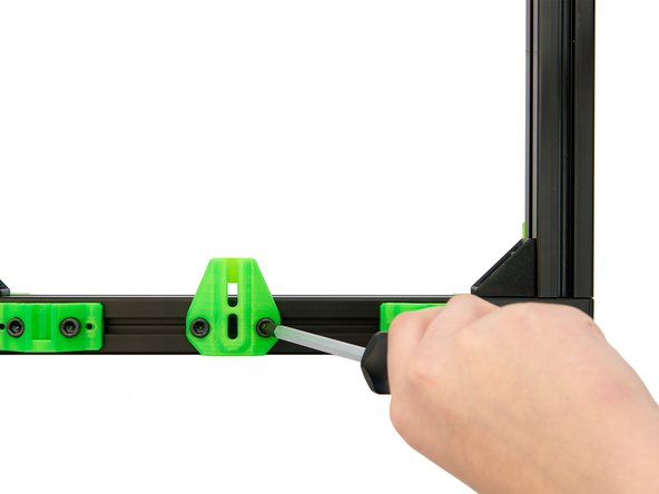
Place the y-belt tensioner on 2x T-Nuts in the front x-axis and fasten it loosely with 2x M6x12mm Hexagon Socket Head Cap Screws.
-
Both the y-motorholder and the y-belt tensioner must be easily movable on the corresponding x-axes.
-
-
-
The setup of the y-axis is now complete.
-
If you are building a printer with MK52 blocks, continue with the manual 03.1. Assembly and Installation of the Heatbed Carriage for MK52-Blocks.
-
If you are building a printer with MK52 carriage, continue with the manual 03.2. Assembly and Installation of the Heatbed Carriage (for MK52)
-


Cancel: I did not complete this guide.
One other person completed this guide.
