
-
-
It is your responsibility to read, understand, and adhere to the applicable documentation for this controller board and any other devices that are to be attached to it.
-
Lack of adherence / compliance to the equipment manufacturer’s documentation and warnings can result in equipment, personnel, and property damage.
-
Do not use any power supply while wiring the board unless you're asked to do so.
-
-
-
High quality crimping tool for mini crimps (e.g. PA-20 or PA-21)
-
Insulation stripping pliers
-
Ferrule crimping pliers
-
and of course some cutting pliers
-
-
-
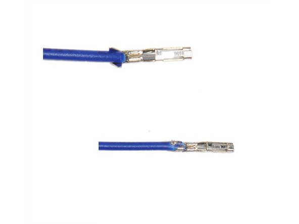
cut-off the old Dupont connectors and unisolate 5mm off the cable.
-
use the 1.9mm slot of the PA-21 to first crimp the wires to the front of the crimping contact.
-
make sure it's fully crimped so that wires are held in place
-
use the 1.9mm slot of the PA-21 to crimp the isolated wire to the back of the crimping contact.
-
make sure it's fully crimped so that cable is held in place
-
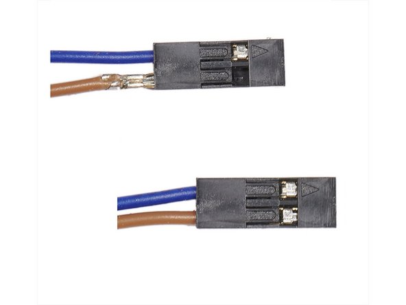
Before inserting the cables in the housing check the position and the orientation
-
Make sure the little "hooks" show up in the litte windows
-
-
-
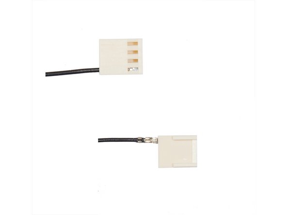
cut-off the old Dupont connectors and unisolate 5mm off the cable.
-
use the 1.6mm slot of the PA-21 to first crimp the wires to from the crimping contact.
-
make sure it's fully crimped so that wires are held in place
-
use the 1.6mm slot of the PA-21 to crimp the isolated wire to the back of the crimping contact.
-
Before inserting the cables in the housing check the position and the orientation
-
Make sure the little "hooks" show up in the litte windows
-
-
-
cut-off the old Y-connector and unisolate 12mm off the cable.
-
twist the wires a bit to make slide easier into the ferrules.
-
Insert the cable into the ferrule and make sure the wires come out at the end
-
use the ferrule crimping tool to crimp the ferrule
-
cut-off the wires at the end and repeat the last step for the second cable
-
final crimped cable
-
for the heat bed cable use the large grey ferrules
-
for the heater cable use the small grey ferrules. You have to cut-off 2mm of the ferrules after crimping to fit the green housing
-
-
-
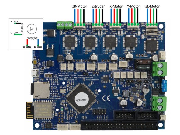
Never attach / detach motors when the board is powered!!
-
Never blindly trust stepper motors’ wiring colors, always check phases. Mixing the phases up on the 4-pin connector can and often does result in damage to the stepper driver. Be especially careful when using stepper motors with detachable cables!
-
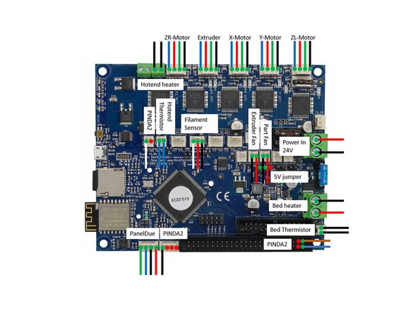
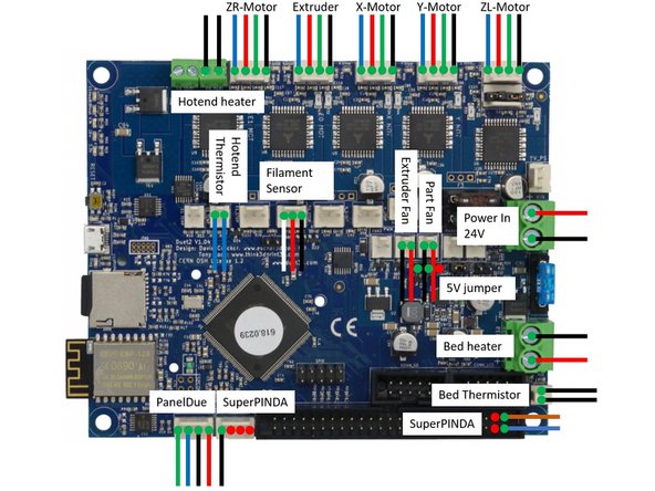
ZR is the right z-motor
-
ZL is the left z-motor
-
Make sure both jumpers are installed.
-
-
-
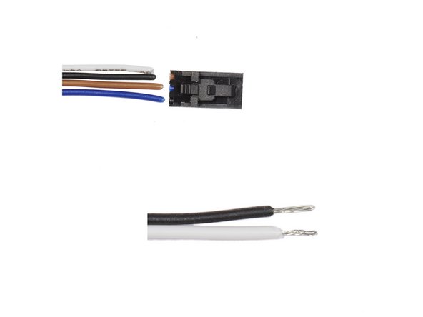
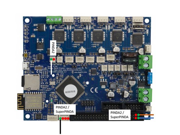
The PINDA2 probe cable needs to be split into three connections:
-
WHITE for temperature sense,
-
BLACK for probe trigger,
-
and power as BROWN +5v & BLUE GND. Make sure to crimp the cables to a 2 pin Dupont housing.
-
The SuperPINDA probe cable needs to be split into two connections:
-
BLACK for probe trigger,
-
and power as BROWN +5v & BLUE GND. Make sure to crimp the cables to a 2 pin Dupont housing.
-
-
-
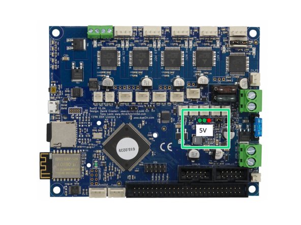
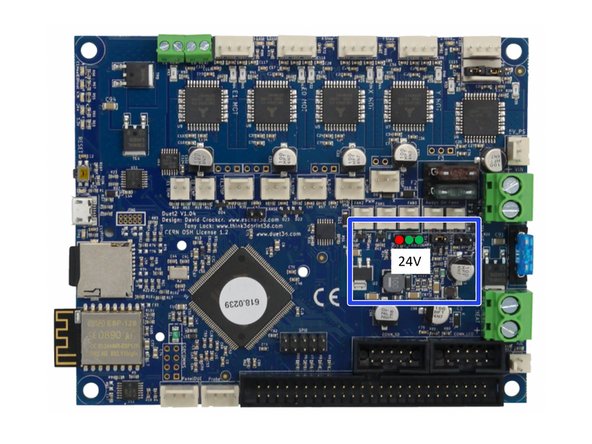
Make sure that the jumper is set according to the voltage of your fans!!!
-
5V position
-
24V position
-
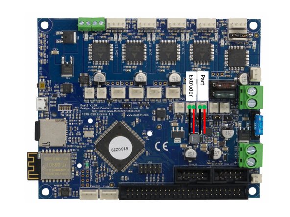
Make sure the polarity of the fans is correct!
-
-
-
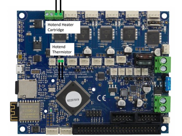
Make sure that you crimp the provided ferrules to the hotend power cables.
-
Polarity of the hotend cartridge does not matter.
-
Polarity of the hotend thermistor does not matter.
-
-
-
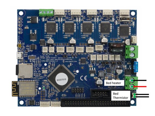
Make sure that you crimp the provided ferrules to the heat bed cables.
-
Pay attention to the polarity of the heated bed. If it's wrong the integrated LED on the bed wil not work.
-
The polarity of the thermistor does not play a role.
-
-
-
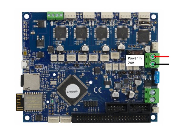
The Duet 2 Wifi board requires only one pair of power cables. If your PSU has two pairs installed remove one pair from the PSU.
-
Make sure that you crimp the provided ferules to the power cables.
-
Pay attention to the polarity. Wrong polarity of the power in cables will destroy the board.
-
-
-
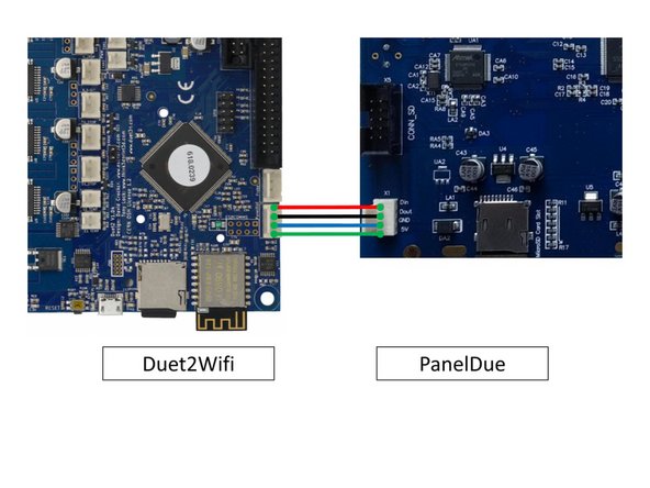
Use the 4-wire cable that comes with the PanelDue to connect the PanelDue to your controller board for the serial and power connections.
-
-
-
In case the extruder turns in the wrong direction mirror the cables, i.e. (blue,redgreen,black) -> (black,green,red,blue)
-


Cancel: I did not complete this guide.
One other person completed this guide.
