-
-
-
-
-
-
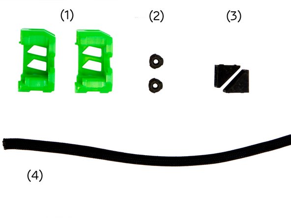
(5) Screw Lock
-
(6) Z-Alignment Tool
-
(7) Lighter
-
-
-
You will need different aluminum profiles, stepper motors and rods depending on your 3D printer model.
-
For a Caribou 220 you will need:
-
(1) 2x 320mm z-Aluminium Extrusion (2) 2x 320mm z-Axis Stepper Motor 1.8° (3) 2x 322mm z-Rod
-
For a Caribou 320 you will need:
-
(1) 2x 420mm z-Aluminium Extrusion 2x 420mm z-Axis Stepper Motor 1.8° (3) 2x 422mm z-Rod
-
For a Caribou 420 you will need:
-
(1) 2x 520mm z-Aluminium Extrusion(2) 2x 520mm z-Axis Stepper Motor 1.8° (3) 2x 522mm z-Rod
-
-
-
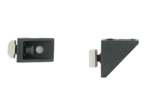
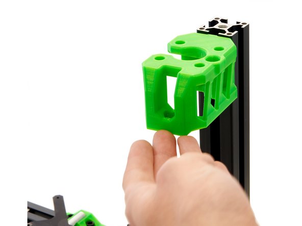
(1) z-Motorholders, left and right
-
(2) 2x Screw Cover
-
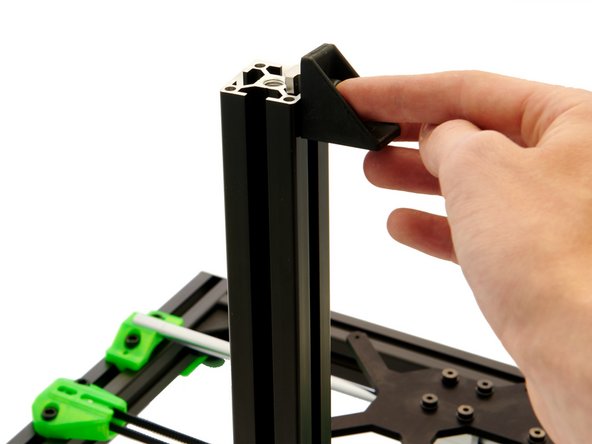
(3) 2x Corner Bracket
-
-
-
-
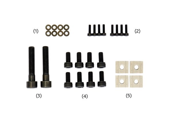
(1) 8x Black Washers
-
-
-
-
(5) 4x T-Nuts
-
-
-
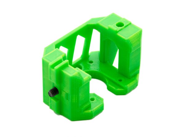
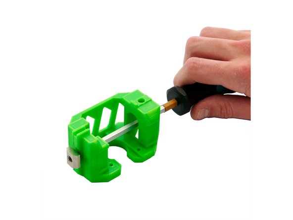
Insert a M6x12mm Hexagon Socket Head Cap Screw into the inside of the z-motor mount and screw a T-Nut to it loosely from the outside.
-
Repeat this step for the second z-motor holder.
-
Place a M6x12mm Hexagon Socket Head Cap Screw in one of the two holes of the corner bracket and screw a T-Nut loosely onto it.
-
Repeat this step for the second corner bracket.
-
-
-
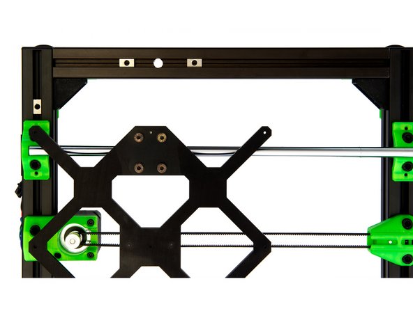
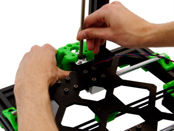
Align the T-Nuts and the y-carriage (see Fig. 1). Make sure that there is one T-Nut in front of the hole and one behind it in each of the y-aluminum extrusions.
-
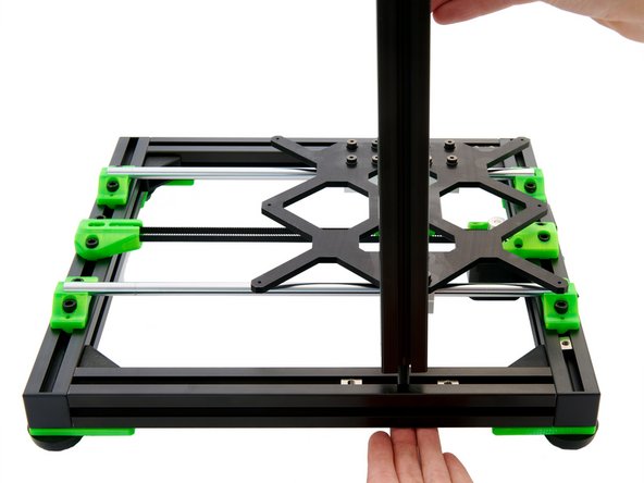
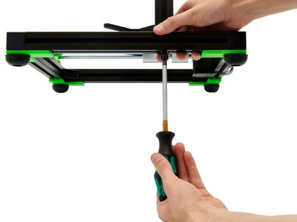
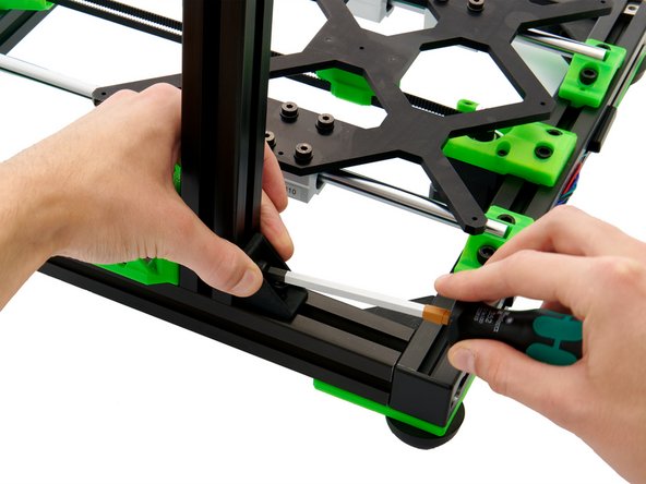
Place your z-extrusion over the hole in the y-extrusion and fix it from below with a M8x40mm Hexagon Socket Head Cap Screw.
-
After tightening, loosen the M8x40mm Hexagon Socket Head Cap Screw just enough so that the profile can still be moved easily in all directions.
-
-
-
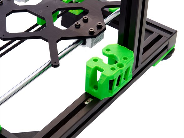
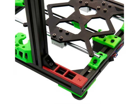
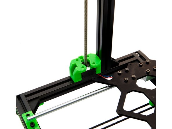
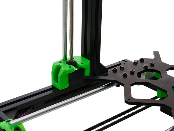
Slide the z-motor holder (the opening must face inwards) into the front slot of the z-extrusion. Then, press the z-motor holder onto the y-extrusion so that it rests straight on it.
-
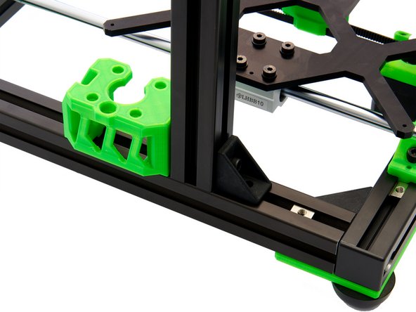
Slide a corner bracket into the rear slot of the z-extrusion.
-
-
-
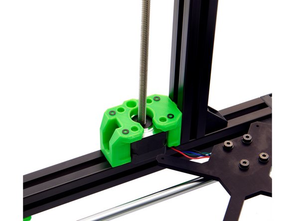
Press the z-extrusion onto the surface of the y-extrusion so that the corner angle rests squarely on it.
-
Now, tighten the previously attached M6x12mm Hexagon Socket Head Cap Screw to the z-motor mount and the corner bracket.
-
-
-
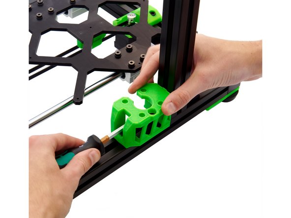
Position the 2x T-Nuts on the y-extrusion under the opening of the z-motor mount and under the hole in the corner bracket.
-
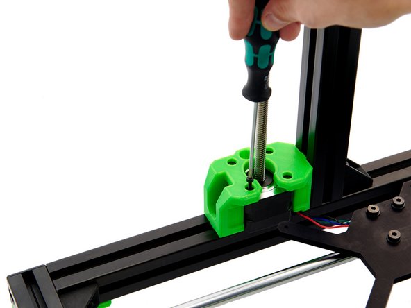
Take 2x M6x12mm Hexagon Socket Head Cap Screws and screw them loosely into the 2x T-Nuts.
-
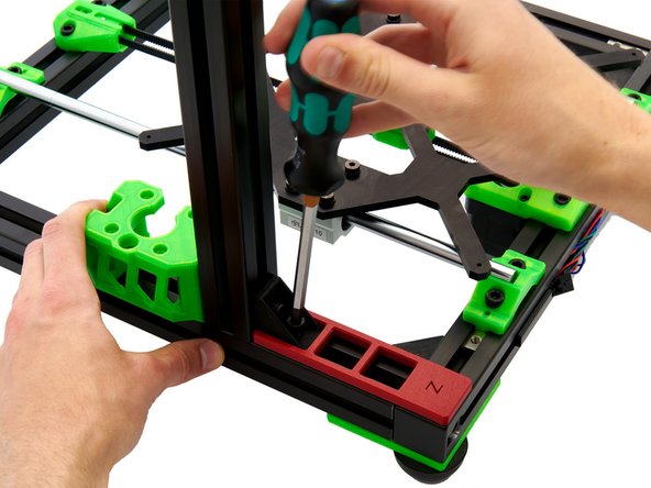
Place the z-alignment tool on the rear part of the x-extrusion and push the z-extrusion against it until it touches the tool.
-
Now, fasten both the M6x12mm Hexagon Socket Head Cap Screwattaching the corner bracket, and the M8x40mm Hexagon Socket Head Cap Screw.
-
The M6x12mm Hexagon Socket Head Cap Screw on the z-motor mount remains loose for the time being.
-
Repeat steps 6 and 7 for the other side of the frame.
-
-
-
First, you have to distinguish between right and left z-stepper motor. The right z-stepper motor comes with a long cable and the left one with a short cable.
-
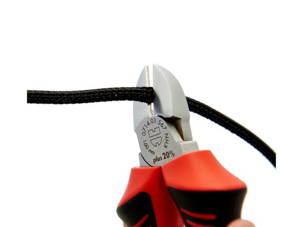
Cut 15cm and 60cm from your Techflex tube. The remaining 25cm are used in manual 10.
-
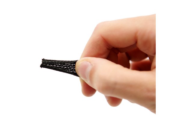
The two ends of the Techflex tube are briefly heated with a lighter.
-
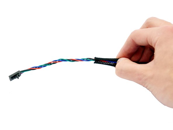
Now, push the motor cable of the left z-stepper motor through the 15cm Techflex hose and the motor cable of the right z-stepper motor through the 60cm Techflex tube.
-
-
-
First, remove the POM nuts from the two z-stepper motors and set them aside. They will later be needed for the construction of the x-axis.
-
Place the z-stepper motor next to the z-motor holder. The cable should be aligned towards the rear of the frame.
-
Carefully slide the z-stepper motor into the z-motor mount and make sure that the cables are not pinched.
-
Press the z-stepper motor up from below until it snaps in.
-
Place 4x M3 Washers in the z-motor mount.
-
-
-
Screw the z-stepper motor to the motor mount using 4x M3x10mm Hexagon Socket Head Cap Screws.
-
Make sure that the z-stepper motor is completely straight.
-
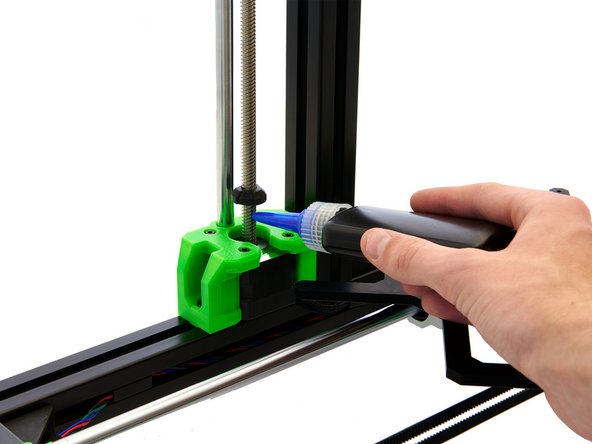
Now, push the Techflex tube surrounding the cables attached to the z-stepper motor as far into the z-motor mount as possible.
-
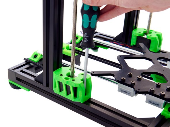
Tighten the M6x12mm Socket Head Cap Screw in the z-motor mount on the y-axis.
-
-
-
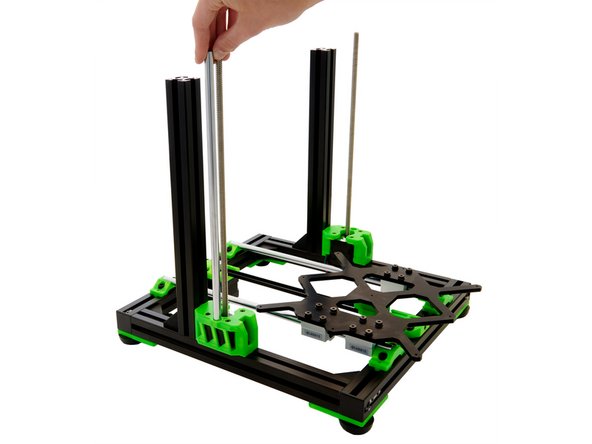
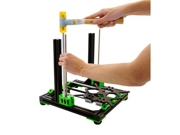
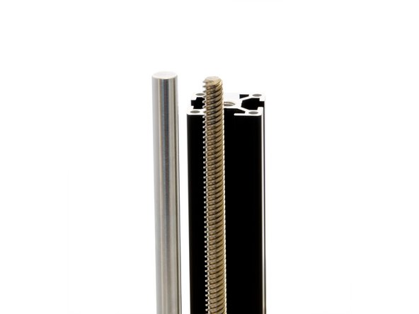
Place a z-rod in the hole next to the z-stepper motor on the z-motor mount. Carefully tap the z-rod straight into place.
-
-
-
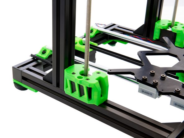
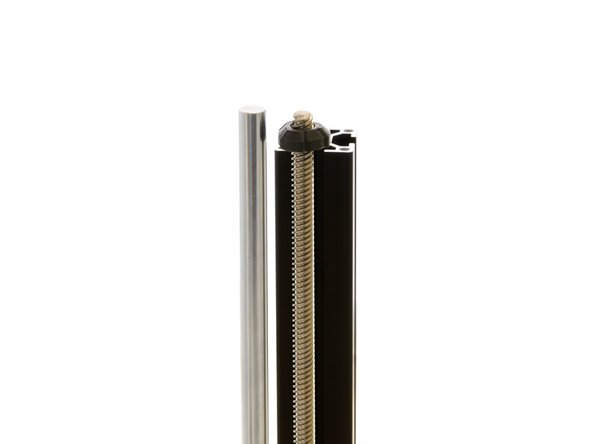
Turn the screw cover onto the z-stepper motor until it is almost at the bottom of the spindle.
-
At the very bottom, put a drop of Screw Lock on the spindle and turn the z-screw cover above it. A gap of 1mm should remain between the bottom of the z-screw cover and the top of the motor.
-
Regularly check whether the screw cover is properly seated. It must not rest directly on the motor which will otherwise be blocked.
-
Repeat steps 7 to 14 for the other side of the frame.
-
-
-
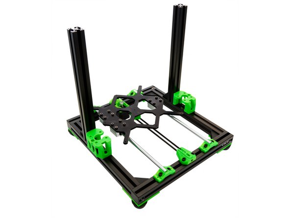
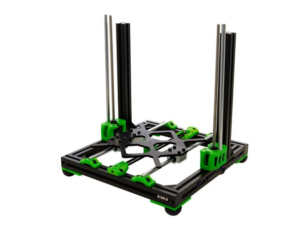
The z-axis is now fully installed.
-
New line.
-
Continue with instructions 06. Assembly of the Duet Box.
-