
Introduction
The term "display" refers to LCDs and OLEDs.
-
-
(1) Display
-
(2) Display Cover
-
(3) Display Mount, left and right
-
(4) Display Knurled Knob
-
(5) 3x Display Cable Clips
-
(6) 2x Display Cables 70cm
-
-
-
-
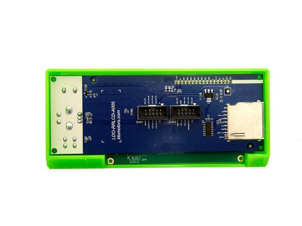
First, remove the protective film from the display, as it cannot be removed from an already assembled display.
-
Place the display in the cover.
-
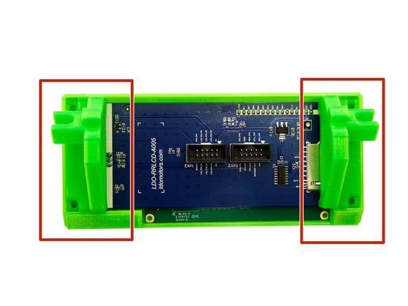
Put the two display mounts into place. Pay attention to the alignment of the mounts (see Fig. 2).
-
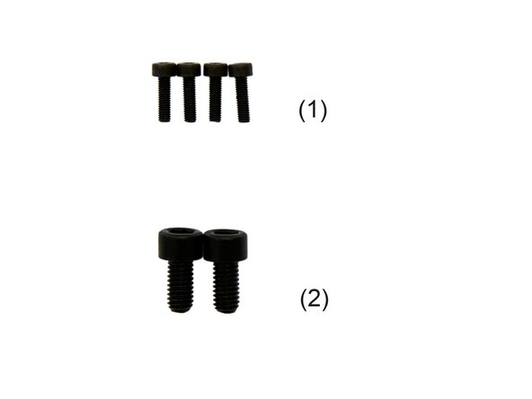
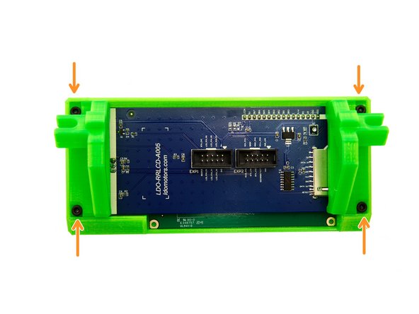
Fasten the mounts with 4x M3x10mm Hexagonal Socket Head Cap Screws.
-
-
-
Push the knurled knob onto the pin. Now, test whether the knob can be pressed down and turned.
-
-
-
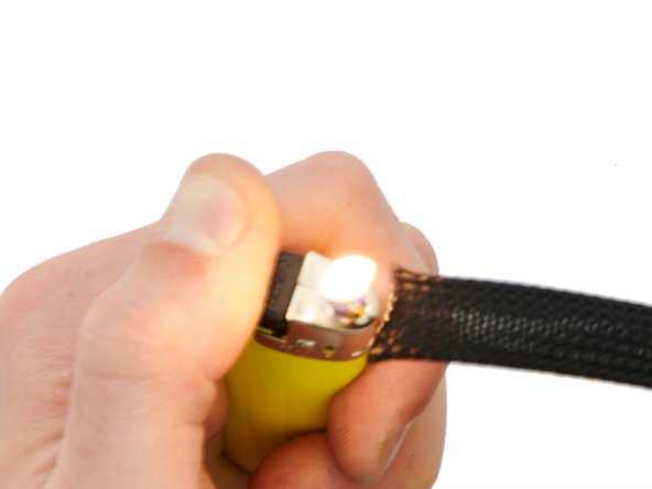
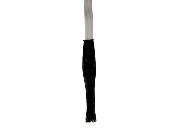
Heat the Techflex tube briefly with a lighter.
-
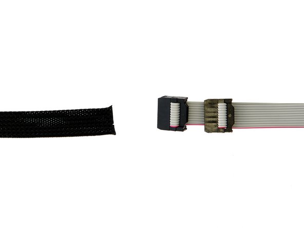
We recommend that you label the two cables 1 and 2 (at both ends) so that they can be easily distinguished later when wiring.
-
Lay the two cables flat on top of each other so that the plugs are directly behind each other.
-
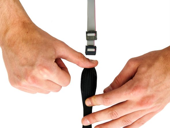
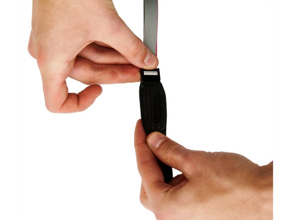
Now, push the cables through the cable tube.
-
-
-
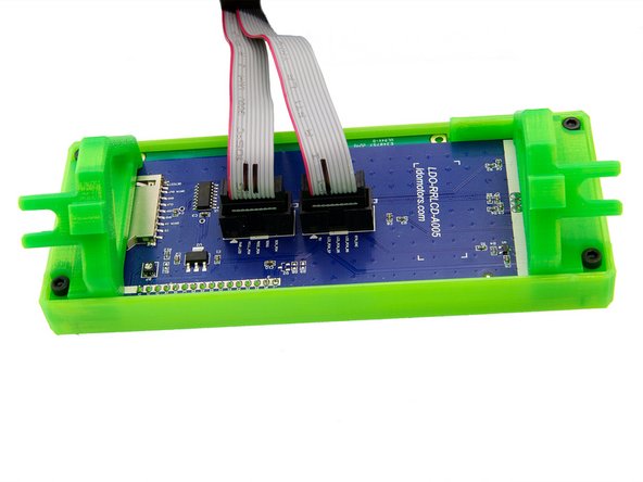
First, plug the two ribbon cables into the connectors on the back of the display.
-
-
-
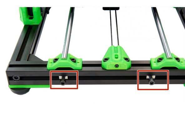
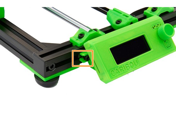
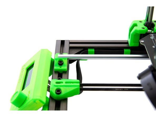
Screw 2x M6x12mm cylinder head screws loosely into the 2x T-nuts , which are located in the front slot of the front x-profile.
-
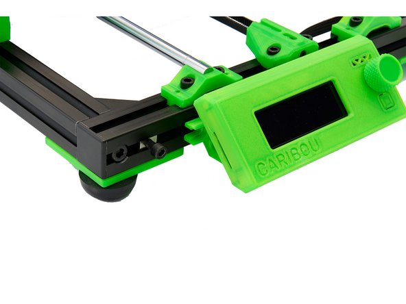
Insert the holders of the display between the two T-nuts.
-
Now slide the T-nuts into the holders using the M6x12mm cylinder head screws.
-
Slide the display to the far left and tighten the 2x M6x12mm cylinder head screws.
-
-
-
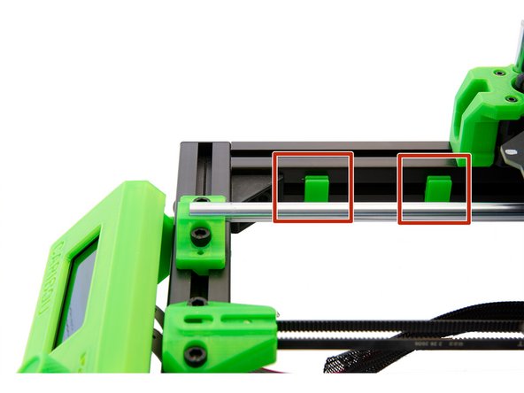
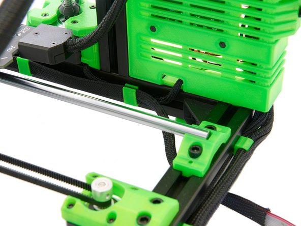
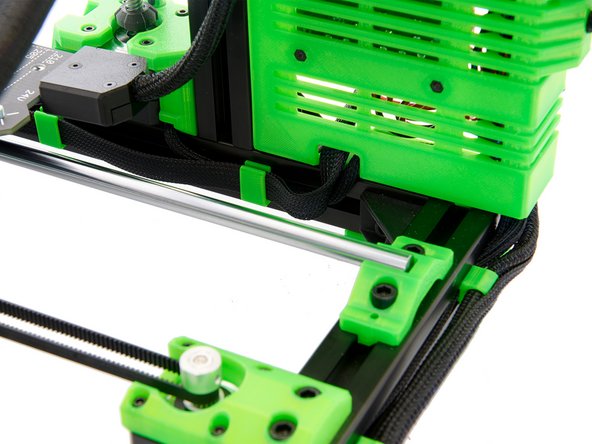
Now attach 2x display cable clips to the front right side of the left y-profile.
-
Now guide the cable of the z-motor into the aluminum profile.
-
Insert another display cable clip into the profile.
-
-
-
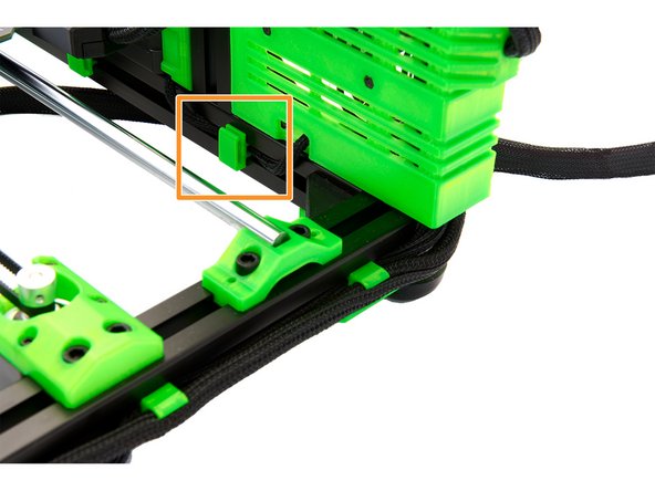
Slide the Techflex sleeve through the cable clips and through the opening in the back of the Einsy Box.
-
The connection to the Einsy board follows in a later step.
-
-
-
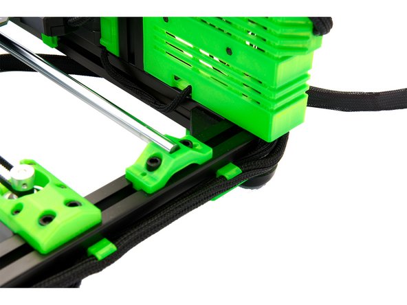
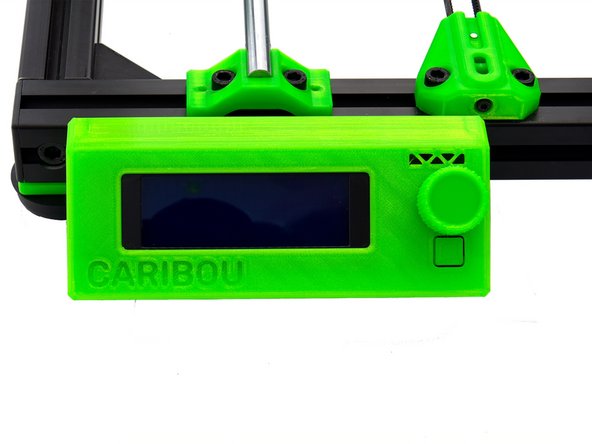
The display is now fully installed.
-
Continue with instructions 10. Wiring of the Motors and the PSU.
-


Cancel: I did not complete this guide.
One other person completed this guide.