-
-
(1) 1.5x60mm Hexagon Socket Head Screwdriver for Electronic Applications
-
-
-
(4) Engineer Scriber
-
-
(6) Super Lube
-
(7) Injectors
-
(8) Isopropanol (optional)
-
-
-
(1) 2x x-Rod 380mm
-
(2) Stepper Motor
-
(3) LMU10 Bushing
-
(4) 3x LMUW10 Bushing
-
-
(6) 2x POM Nut
-
(7) x-Motor Holder
-
(8) x-Idler
-
-
-
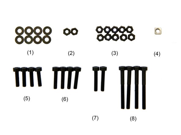
(1) 8x Black M3 Washers
-
(2) 2x M3 Nuts
-
(3) 10x M3 Self-Securing Nuts
-
(4) M3 Square Nut
-
-
-
-
-
-
-
To prepare for later, 3x LMUW10 bushings and one LMU10 bushing must be placed in isopropanol for 15min.
-
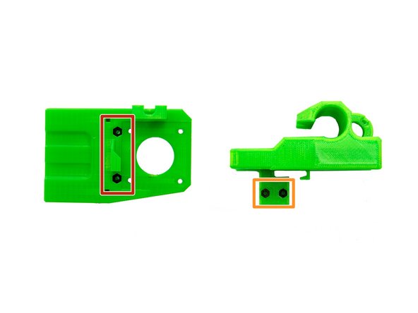
Insert 2x M3 Self-Securing Nuts into the back of the x-motor holder.
-
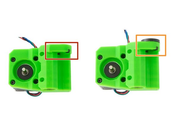
Insert 2x M3 Nuts into the bottom of the cable guide at the back of the x-motor holder.
-
Tighten the 2x M3 Self-Securing Nuts and the 2x M3 Nuts with a screwdriver or an engineer scriber if necessary.
-
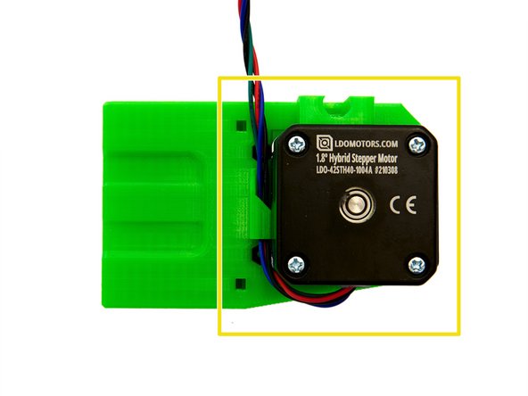
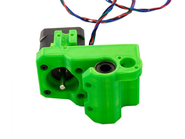
Place a stepper motor on the back of the x-motor holder. When doing so, pay close attention to the alignment (see Fig. 2).
-
Make sure that the cables are routed through the cable holder.
-
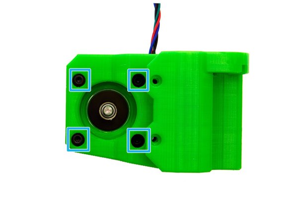
Hold on to the stepper motor and turn the x-motor holder. Place 4x M3 Washers in the four openings of the x-motor holder. Then, fasten the stepper motor to the x-motor holder with 4x M3x12mm Hexagon Socket Head Cap Screws.
-
-
-
Now, you need the bushings you have prepared in the first step. They must be dryed and then greased with Super Lube.
-
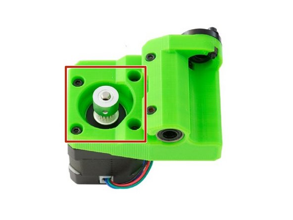
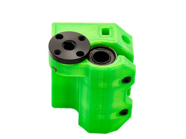
One of the greased LMUW10 bushings is pushed into the x-motor holder so that it is centered. Then the bushing is fixed with 2x M3x30mm Hexagon Socket Head Cap Screws.
-
When doing so, make sure that you only tighten the M3 Hexagon Socket Head Cap Screws minimally so that the screw is flush with the M3 Self-Securing Nuts.
-
-
-
Check the hole for the POM nut for filament protrusions and remove them with a knife or scalpel if necessary.
-
Insert 2x M3 Self-Securing Nuts into the designated slots.
-
Insertion can be made easier with the help of an engineer scriber.
-
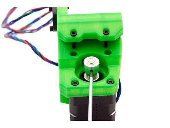
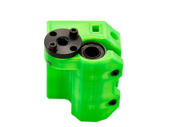
Now place a POM nut in the hole on the top.
-
Use 2x M3 Washers and 2x M3x14mm Hexagon Socket Head Cap Screws to fix the POM nut.
-
Here, make sure that you screw the screws into the threaded holes of the POM nut.
-
Do not tighten the 2x M3x14mm Hexagon Socket Head Cap Screws completely at this stage.
-
-
-
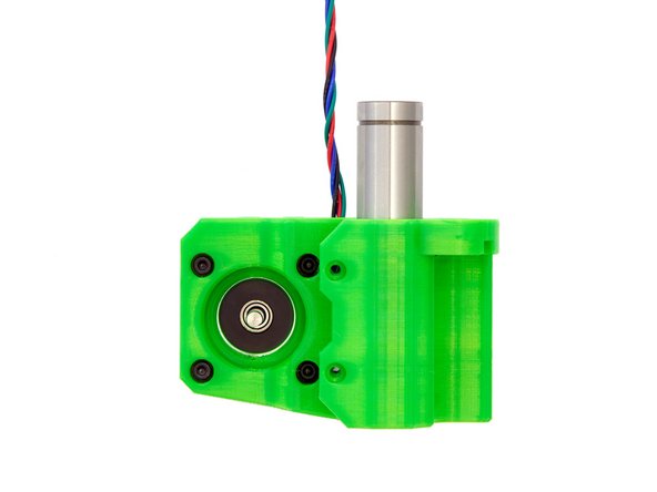
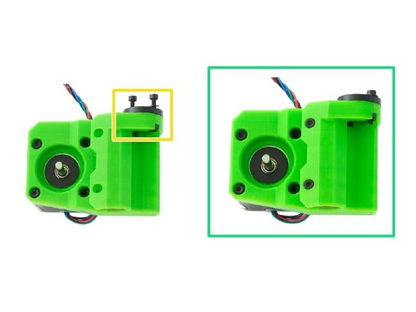
Slide the GT3 pulley onto the shaft of the stepper motor.
-
The motor shaft has two grub screws. Make sure that one of them is aligned with the flat surface of the shaft and tighten both grub screws.
-
Leave a narrow gap between the pulley and the motor surface to avoid friction.
-
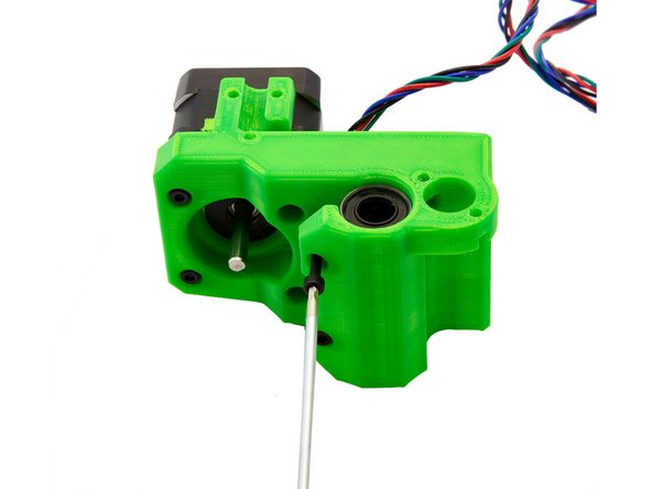
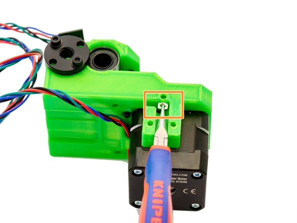
Insert a M3 Square Nut into the slot on the back of the x-motor holder using electronics pliers
-
The x-motor mount is now fully assembled.
-
-
-
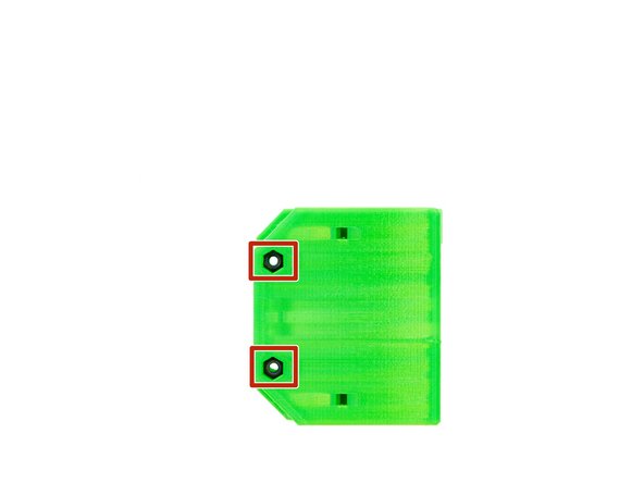
Insert 2x M3 Self Securing Nutsinto the back of the x-idler.
-
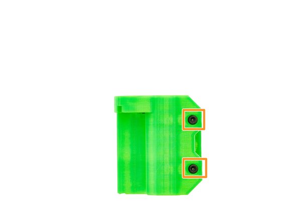
Insert 2x M3 Self-Securing Nutsinto the two slots on the top and bottom of the x-idler and lightly tightened them with 2x M3x16mm Hexagon Socket Head Cap Screws.
-
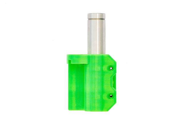
Push one of the greased LMUW10 bushings into the x-idler and ensure that it is centered.
-
Fasten it with 2x M3x30mm Hexagon Socket Head Cap Screws .
-
Make sure that you tighten the Hexagon Socket Head Cap Screws only minimally, as they should fit flush with the M3 Self-Securing Nuts.
-
-
-
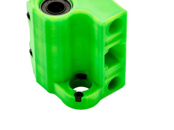
Check the hole for the POM nut for filament protrusions and remove them with a knife or scalpel if necessary.
-
Insert 2x M3 Self-Securing Nutsinto the designated slots.
-
Insertion can be made easier with the help of an engineer scriber.
-
Now, put a POM Nut into the hole on the top.
-
Take 2x M3 Washers and 2x M3x14mm Hexagon Socket Head Cap Screws to fix the POM nut.
-
Make sure that you screw the screws into the two threaded holes of the POM nut.
-
Do not tighten the 2x M3x14mm Hexagon Socket Head Cap Screws completely for the time being.
-
The x-idler is now fully assembled.
-
-
-
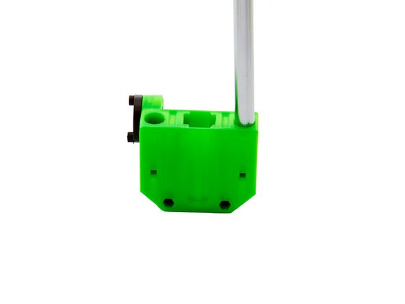
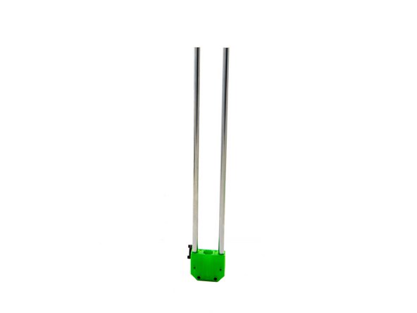
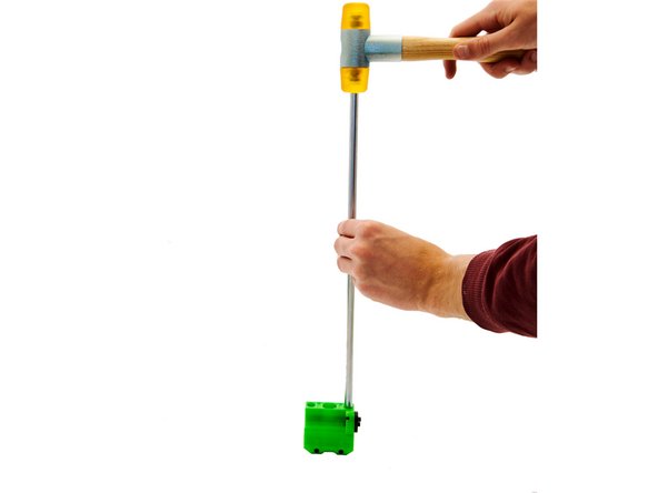
Place one of the 380mm x-Rods into one of the designated holes. Carefully tap the rod into the x-idler with a soft-faced hammer.
-
Repeat this step with the second rod.
-
Make sure the rods are pushed in all the way down by looking through the small window on the back of the x-idler.
-
-
-
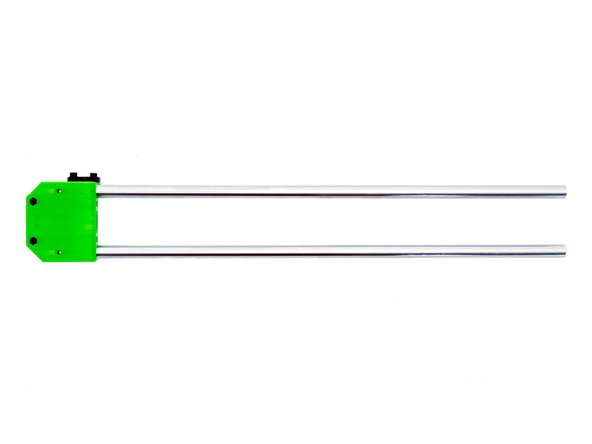
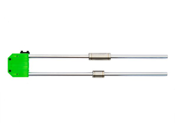
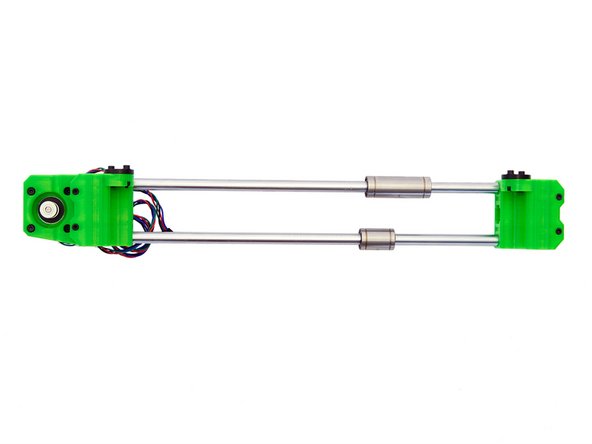
Align the x-axis as shown in the first picture. Slide an LMUW10 bushing onto the upper x-rod and an LMU10 bushing onto the lower x-rod.
-
Remember to grease the bushings with Super Lube beforehand.
-
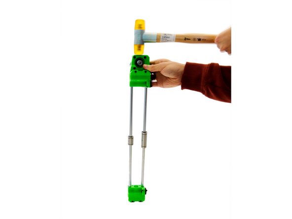
Align both x-rods with the holes in the x-idler and gently tap the x-idler with a soft-faced hammer.
-
The x-Idler has a small window on the back that allows you to check whether the rods are properly positioned.
-
-
-
The assembly of the x-axis is completed now.
-
Continue with instructions 13. Installation and Wiring of the x-Axis.
-