-
-
-
-
-
-
(5) Caliper 300mm
-
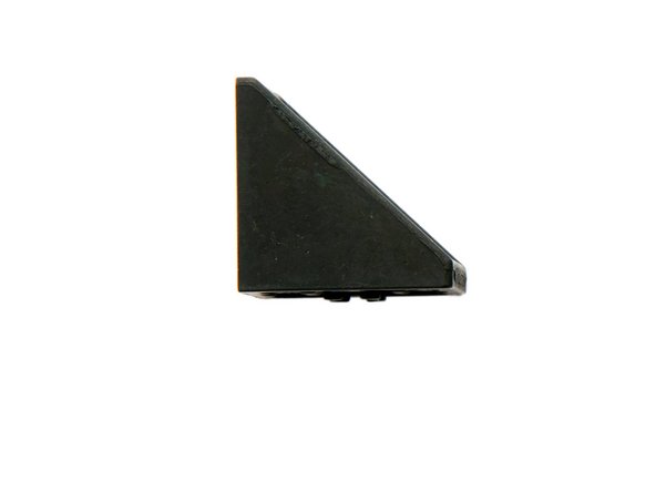
(6) Stop Angle
-
-
-
-
(2) 9x T-Nuts
-
-
(4) 2x End Caps
-
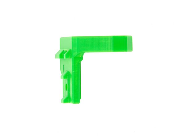
(5) 2x Corner Brackets
-
(6) 2x z-Top Mount, left and right
-
-
-
-
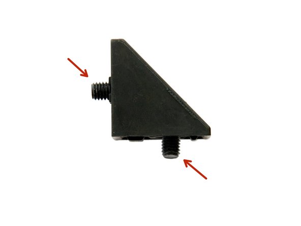
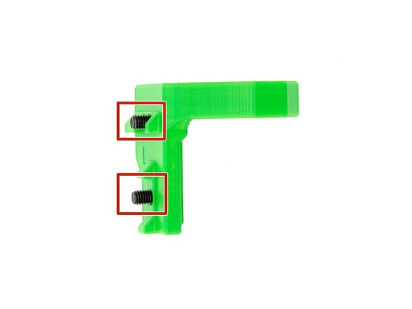
Insert 2x M6x12mm Hexagon Socket Head Cap Screws into a corner bracket.
-
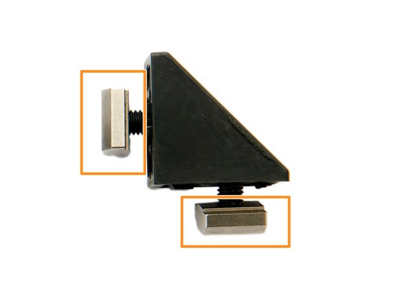
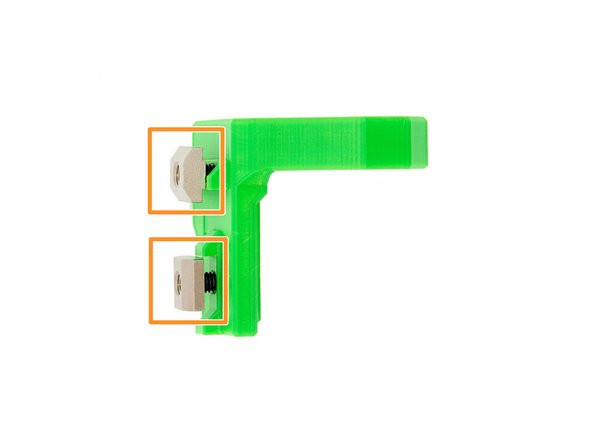
Screw them loosely to the corner bracket using 2x T-Nuts.
-
Pay attention to the alignment of the T-Nuts (Fig. 3).
-
Repeat this step for the other corner bracket.
-
-
-
Place 2x M6x12mm Hexagon Socket Head Cap Screws in one of the z-top mounts.
-
Screw them loosely to the z-mounts with 2x T-Nuts.
-
Pay attention to the alignment of the T-Nuts (Fig. 3)
-
Repeat this step for the other z-top mount.
-
-
-
Slide one of the corner brackets into the right slot of the left z-extrusion so that the end of the extrusion and the corner bracket are level.
-
Now tighten the M6x12mm Hexagon Socket Head Cap Screws in the corner bracket on the Z-axis.
-
Repeat this step on the right side.
-
-
-
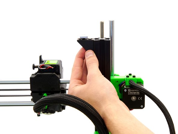
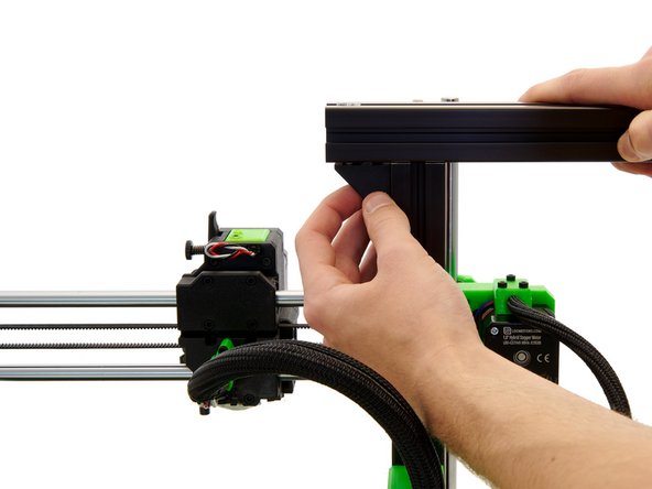
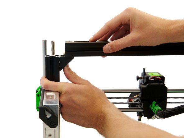
Push the x-extrusion through the two T-Nuts.
-
Make sure that the large holes in the x-extrusion are pointing up and the small holes are pointing down.
-
-
-
Loosen the 2x M6x12mm Hexagon Socket Head Cap Screws in the corner brackets on the z-axis.
-
Insert 2x M8x40mm Hexagon Socket Head Cap Screws into the x-axis and tighten them hand-tight.
-
-
-
Then press the two corner brackets against the x-axis and retighten the 2x M6x12mm Hexagon Socket Head Cap Screws.
-
Remove the 2x M8x40mm Hexagon Socket Head Cap Screws from the x-axis.
-
The x-axis should now be movable to the right and left.
-
-
-
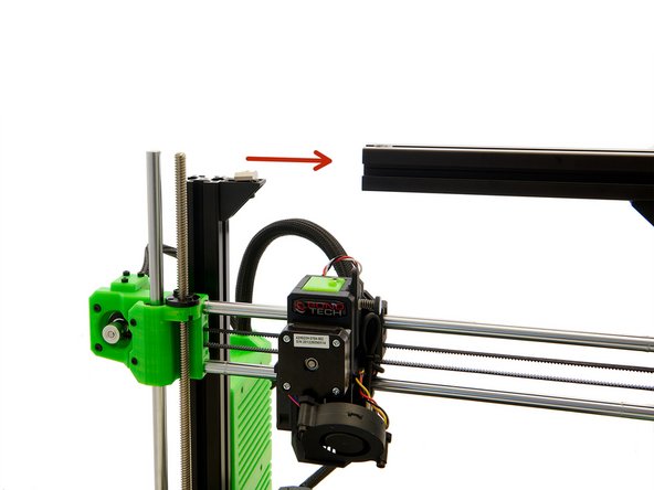
Move the x-axis to the right.
-
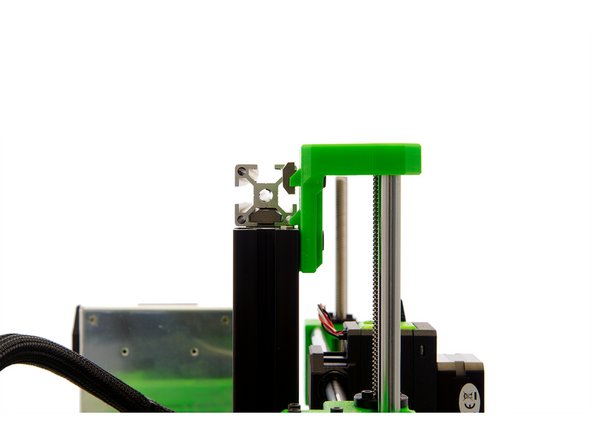
Slide the left z-top mount into the front slot of the left z-axis using the lower T-Nut.
-
Carefully position the left hole in the z-top mount over the z-rod.
-
-
-
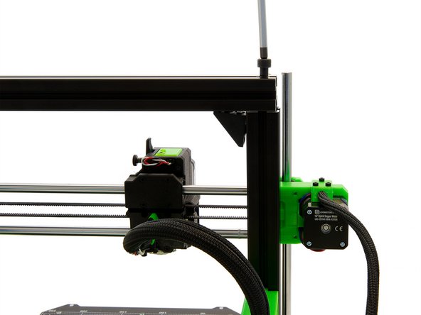
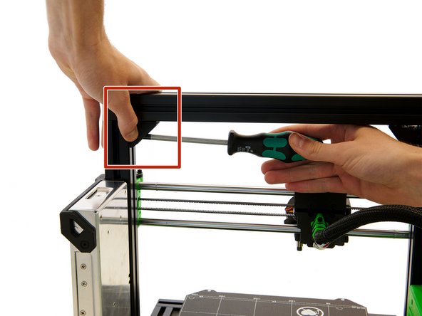
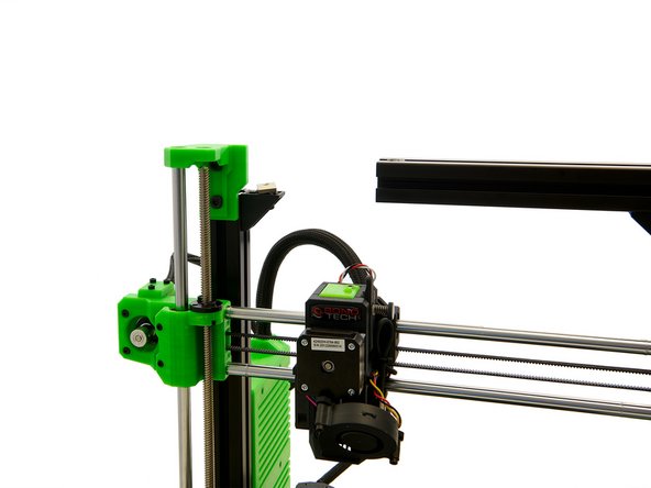
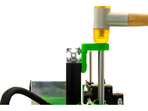
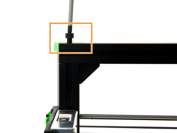
Gently tap the z-top mount with a hammer so that it is at the same height as the z-axis.
-
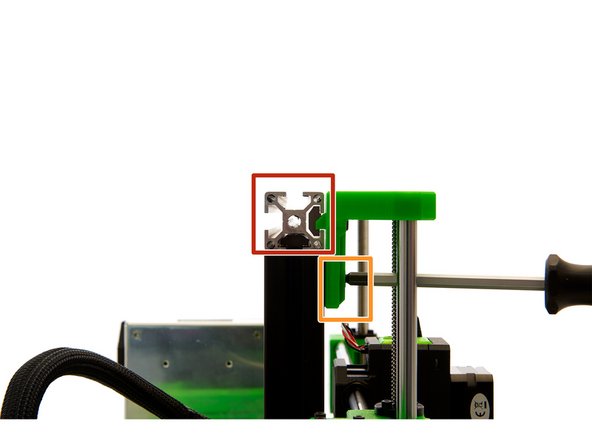
Slide the x-axis over the T-Nut and make sure that the Nut and the T-Nut are at the same level.
-
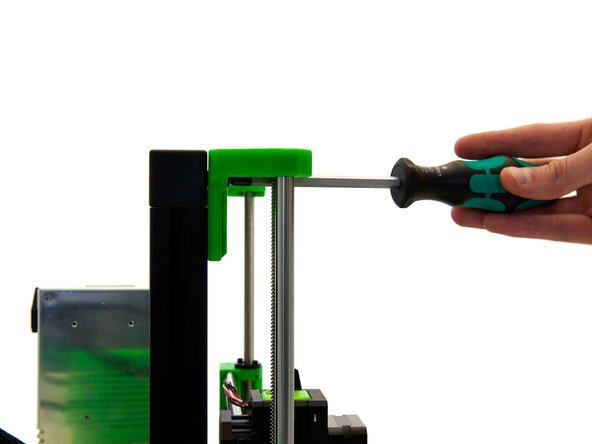
Now, tighten only the lower M6x12mm Hexagon Socket Head Cap Screw.
-
Repeat these two steps for the right z-top mount.
-
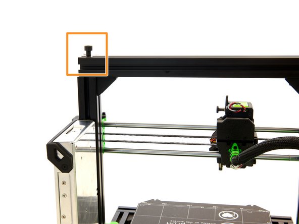
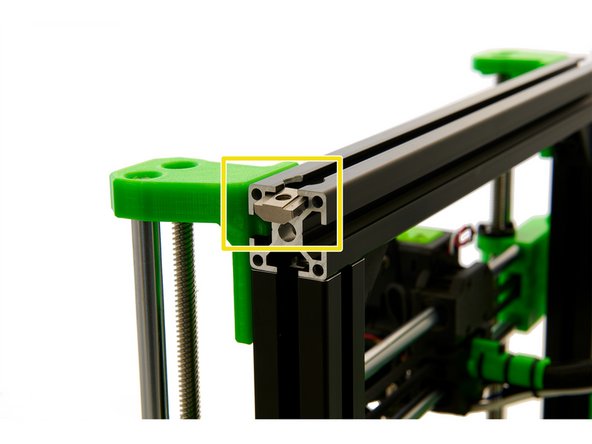
Place a T-Nut in the upper slot of the x-axis.
-
-
-
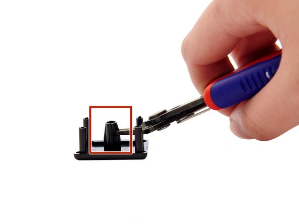
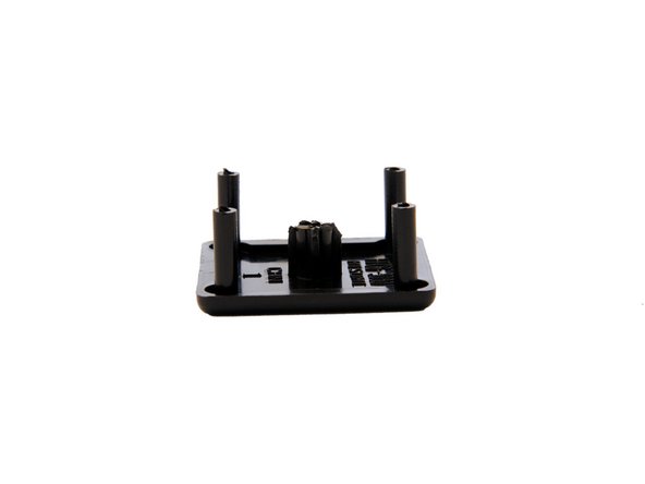
Now, prepare the 2x End Caps by shortening the center part by half (e.g. using a side cutter).
-
Be careful not to cut off too much or the end caps will not hold on the axis.
-
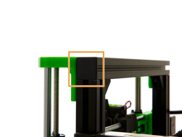
Finally, attach both end caps to the ends of the x-axis.
-
-
-
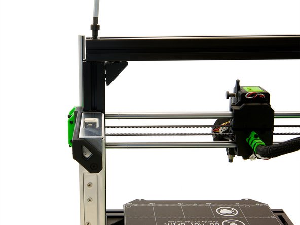
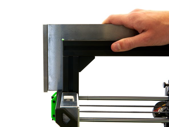
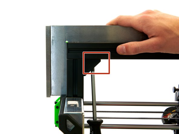
Use a stop angle to ensure that the x- and z-axes are at a 90° angle to each other.
-
Tighten the M6x12mm Hexagon Socket Head Cap Screw in the corner bracket on the x-axis.
-
Tighten the M8x40mm Hexagon Socket Head Cap Screw in the x-axis.
-
Repeat this step on the other side.
-
Then re-check to make sure that the x- and z-axes are at a 90° angle to each other.
-
If this is not the case, you have to align the x-axis again.
-
-
-
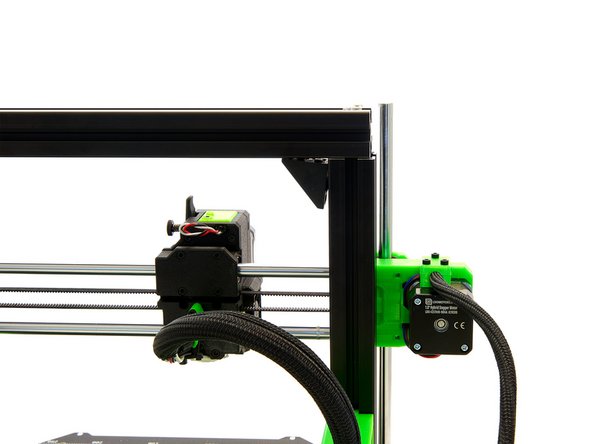
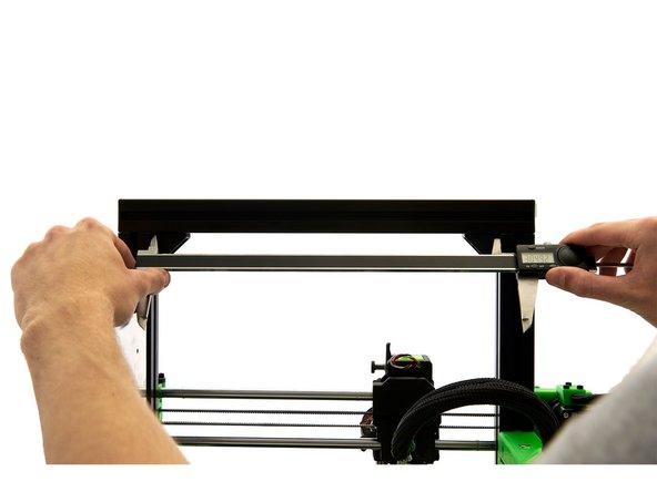
Once you have successfully aligned your x-axis, use a caliper to measure the distance between the two z-axes.
-
To do this, place the caliper at the corner brackets.
-
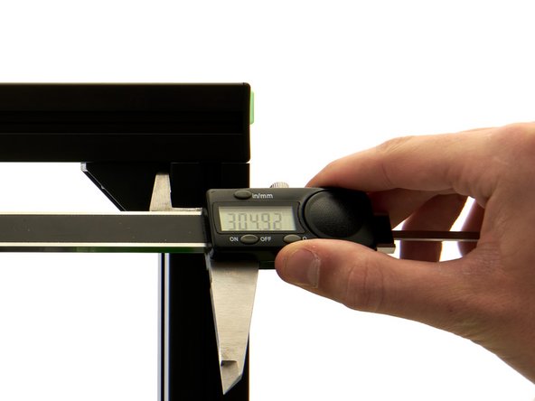
The distance between the two z-axes must range between 304.90 - 305.50mm.
-
The measured value between the two z-axes and those of the xy-frame, must not exceed a difference of 0.05mm.
-
If the difference of their values is > 0.05mm, you have to re-align the frame (see Step 11).
-
If the difference of their values is < 0.05mm, insert and tighten the 2x M8x40mm Hexagon Socket Head Cap Screws into the x-axis.
-
If necessary, tighten these two screws with a torque wrench set to 2.5NM.
-
To check this, measure the distance between the z-axes again. If these values are < 0.05mm, continue with Step 13. Otherwise, you have to loosen the 2x M8x40mm Hexagon Socket Head Cap Screws again and re-align the x-axis (see Step 11).
-
-
-
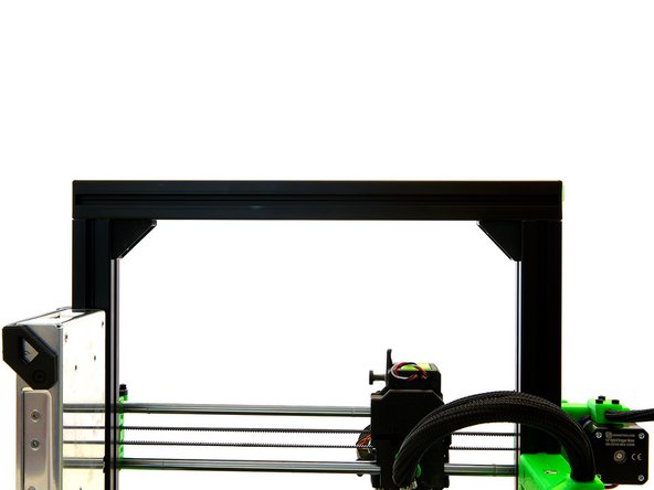
The installation of the upper x-profile is completed now.
-
Continue with instructions 18. Assembly and Installation of the Spoolholder.
-