
-
-
It is your responsibility to read, understand, and adhere to the applicable documentation for this controller board and any other devices that are to be attached to it.
-
Lack of adherence / compliance to the equipment manufacturer’s documentation and warnings can result in equipment, personnel, and property damage.
-
Do not use any power supply while wiring the board unless you're asked to do so.
-
Find more details on how crimp wires and required tools here: CaribouDuet2Wifi/LAN Wiring Guide.
-
-
-
If you have the WiFi version of the Duet 3 Mini 5+, don't forget to connect the external antenna. Ideally, mount the antenna and Duet on your machine first.
-
The antenna connector is quite a tight fit, and is not intended for frequent connecting/disconnecting.
-
Carefully align the connector as square and straight as you can before firmly pushing on.
-
You can also unscrew the aerial from the other end of the cable, which you'll need to do to mount the antenna, and leave the other end connected to the Duet.
-
The antenna mounts through a 1/4" or 6.3mm hole.
-
The antenna is not shown in the forthcoming photos.
-
-
-
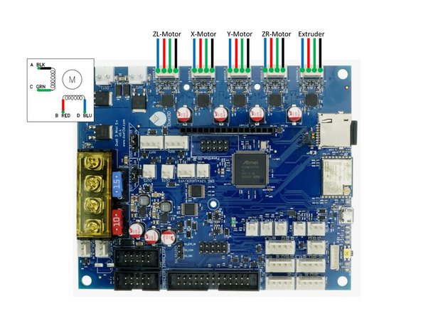
Never attach / detach motors when the board is powered!!
-
Never blindly trust stepper motors’ wiring colors, always check phases. Mixing the phases up on the 4-pin connector can and often does result in damage to the stepper driver. Be especially careful when using stepper motors with detachable cables!
-
ZR is the right z-motor.
-
ZL is the left z-motor.
-
-
-
The PINDA2 probe cable needs to be split into three connections:
-
WHITE for temperature sense,
-
BLACK for probe trigger,
-
and power as BROWN +5v & BLUE GND. Make sure to crimp the cables to a 2 pin Dupont housing.
-
The SuperPINDA probe cable needs to be split into two connections:
-
BLACK for probe trigger,
-
and power as BROWN +5v & BLUE GND. Make sure to crimp the cables to a 2 pin Dupont housing.
-
-
-
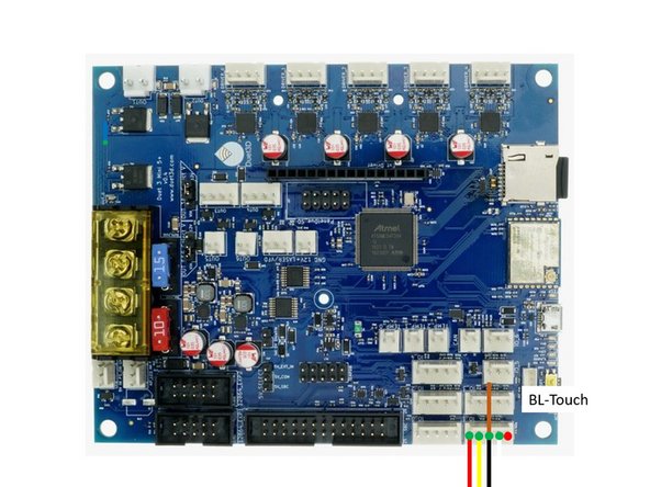
The 5 cables of the BT-Touch need to be crimped and fit into a 5 hole connector.
-
The BL-Touch has 2 ground wires (black and brown). The need to be crimped together to the middle mount of the connector.
-
-
-
On the Duet3Mini+ you can use fans that use VIN (here 24V) or 12V.
-
Make sure that you set the jumper into the correct position for your fans. If it is in the wrong position it it could damge the fans and the board!
-
-
-
Make sure that the jumper is set according to the voltage of your fans!!!
-
Make sure the polarity of the fans is correct!
-
-
-
Polarity of the hotend cartridge does not matter.
-
Polarity of the hotend thermistor does not matter.
-
-
-
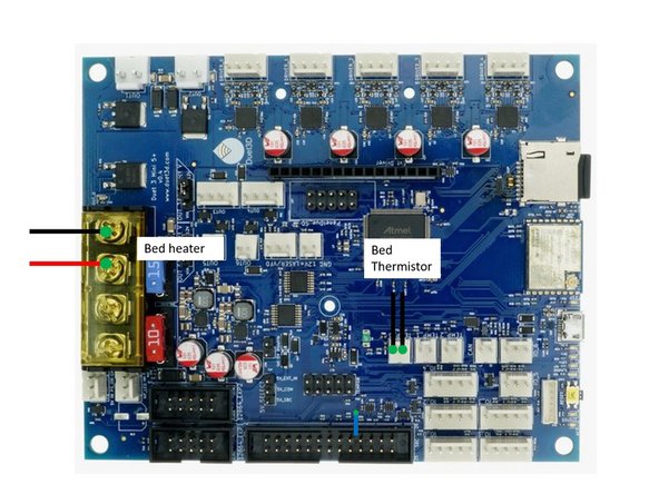
Pay attention to the polarity of the heated bed. If it's wrong the integrated LED on the bed wil not work.
-
The polarity of the thermistor does not play a role.
-
-
-
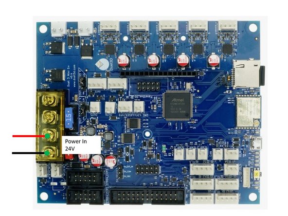
The Duet3Mini+ board require only one pair of power cables. If your PSU has two pairs installed remove one pair from the PSU.
-
Make sure that you crimp the provided ferules to the power cables.
-
Pay attention to the polarity. Wrong polarity of the power in cables will destroy the board.
-
-
-
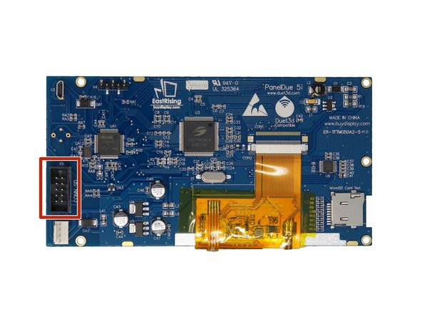
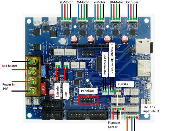
Use a 10pin ribbon cable to connect the Duet3Mini5+ to the PanelDue.
-
-
-
In case the extruder turns in the wrong direction mirror the cables, i.e. (blue,redgreen,black) -> (black,green,red,blue).
-
-
-
In case the extruder turns in the wrong direction mirror the cables, i.e. (blue,redgreen,black) -> (black,green,red,blue).
-


Cancel: I did not complete this guide.
One other person completed this guide.
