-
-
(1) 1.5x60mm Hexagon Socket Head Screwdriver for Electronic Applications
-
-
-
(4) Scalpel
-
-
(6) Pliers Wrench
-
(7) Engineer Scriber
-
(8) Countersink
-
-
-
-
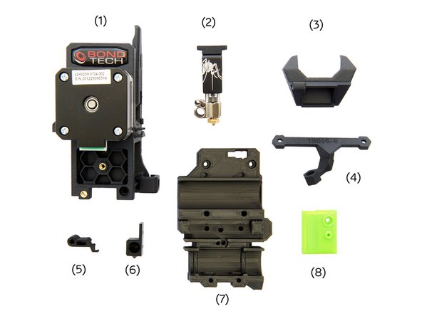
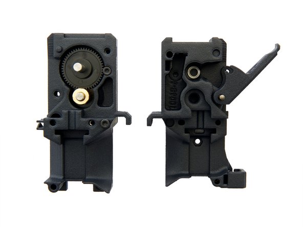
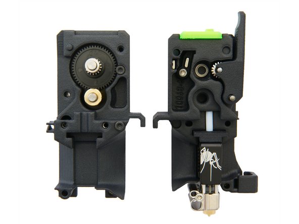
(2) Slice Engineering Hotend Mosquito/ Mosquito Magnum (see manual 14.1.)
-
(3) Fan Shroud (Lüfterauslass)
-
(4) Fan Holder
-
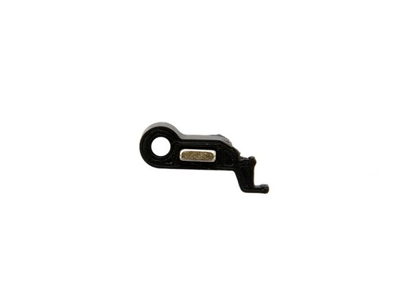
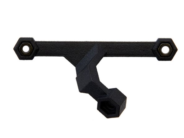
(5) Lever
-
(6) Ball Holder
-
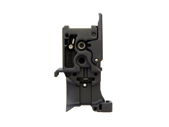
(7) x-Carriage
-
(8) Sensor Cover
-
-
-
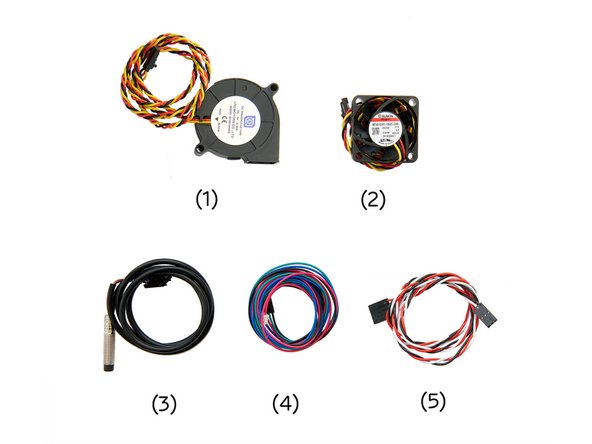
(1) Radial Fan
-
(2) Sunon Fan
-
(3) SuperPINDA /Pinda 2
-
-
(5) Motor Cable
-
-
-
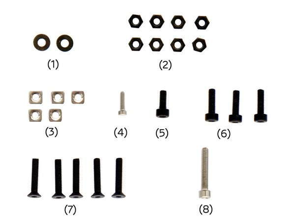
(1) 2x Black Washers
-
(2) 8x M3 Nuts
-
(3) 5x M3 Square Nuts
-
-
-
-
-
-
-
-
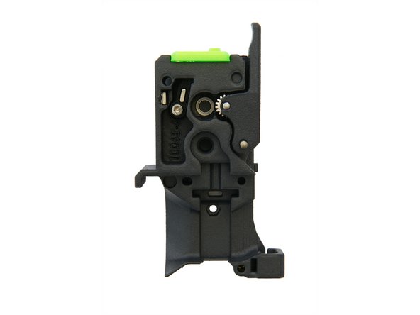
Open the extruder.
-
Insert the small magnet into the lever.
-
If the magnet is loose, fix it with a little super glue. If the magnet is difficult to insert, we recommend using a pliers wrench.
-
Place the lever in the extruder back (the one without motor) and secure it with a M3x18mm Hexagon Socket Head Cap Screw (silver).
-
Now, loosen the screw until the lever can be moved freely.
-
-
-
Insert the long magnet into the slot to the left of the lever.
-
Make sure that the two magnets repel each other.
-
If the magnet is still movable in the slot, fix it with super glue.
-
You can now test the mobility of the lever through the opening for the filament.
-
-
-
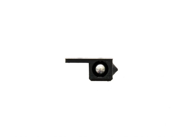
Take the ball holder and check the hole for filament residues. If there are any residues, remove them carefully (e.g. with a scalpel).
-
Insert the 7mm steel ball into the holder.
-
Insert the holder with ball into the top of the extruder back.
-
-
-
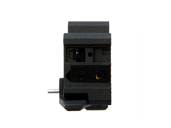
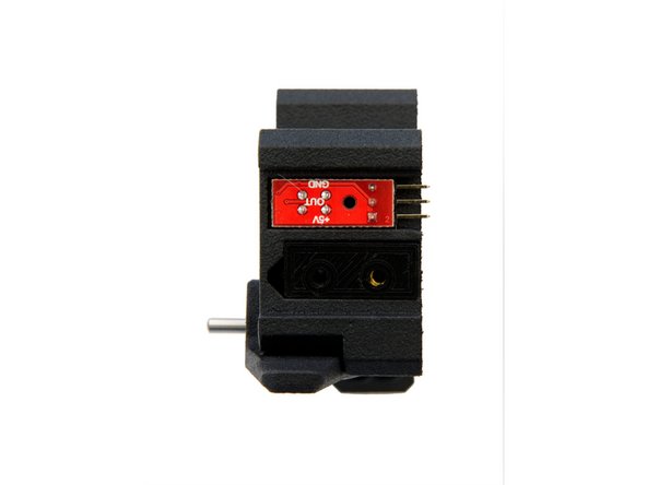
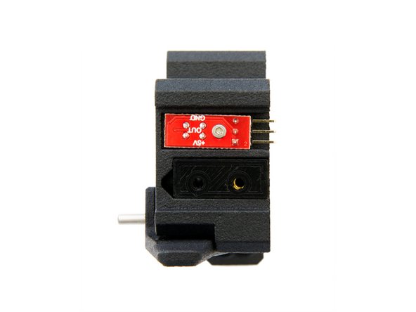
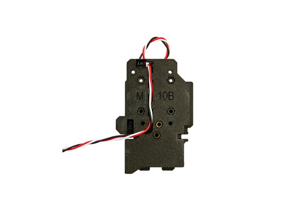
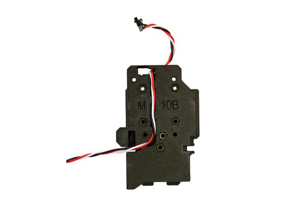
Insert the filament sensor and secure it with the M2x8mm Hexagon Socket Head Cap Screw (silver).
-
Test the mobility of the lever again.
-
If the lever's mobility is compromised, loosen the screw on the filament sensor minimally or check the lever for filament residue, removing it if necessary.
-
Test the mobility of the lever again.
-
Now, place the sensor cover on top and secure it with a M3x10mm Hexagon Socket Head Cap Screw.
-
-
-
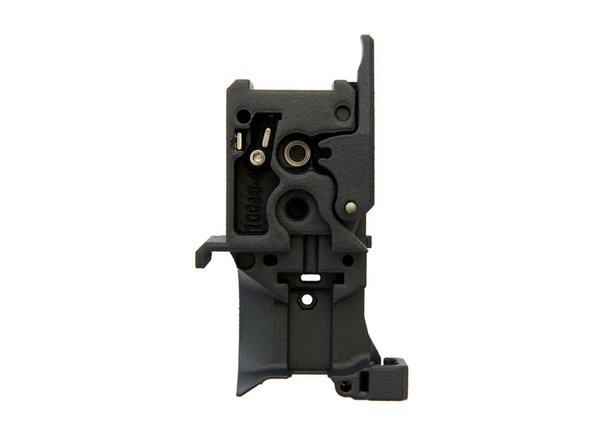
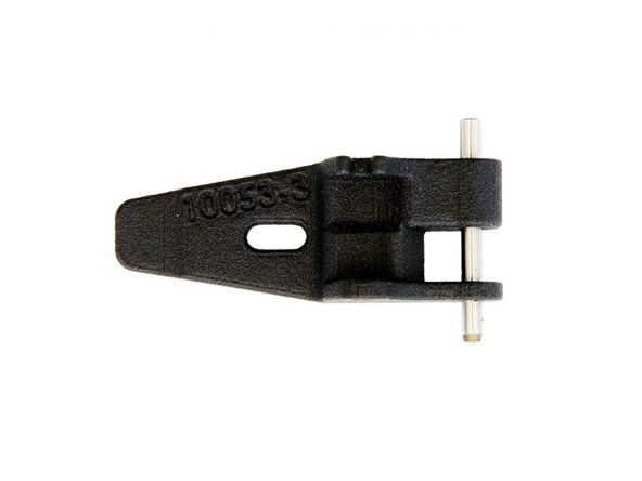
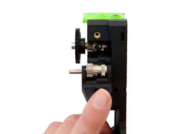
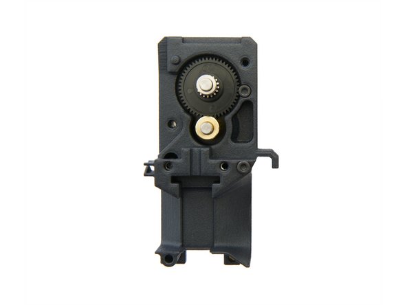
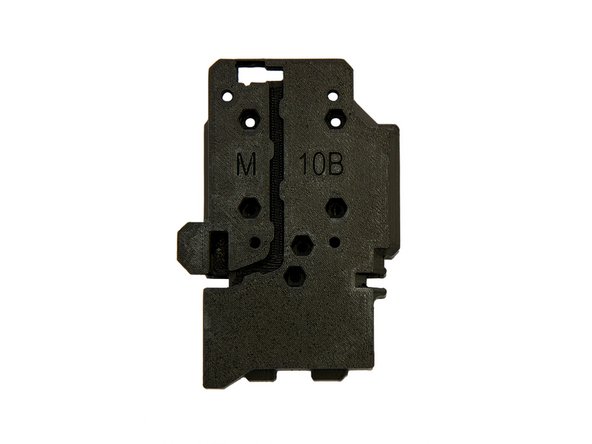
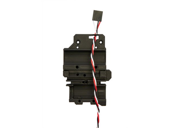
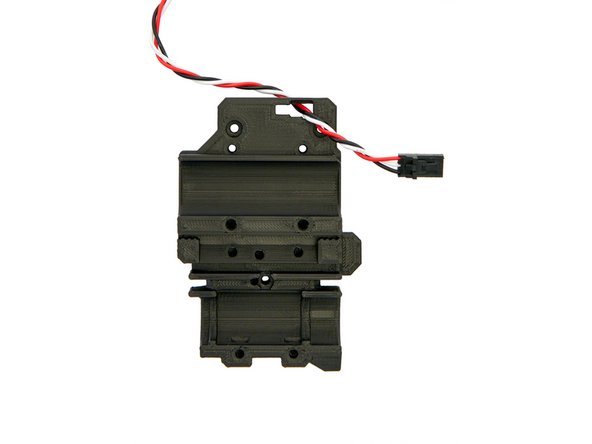
Remove the hinge and shaft from the back of the extruder.
-
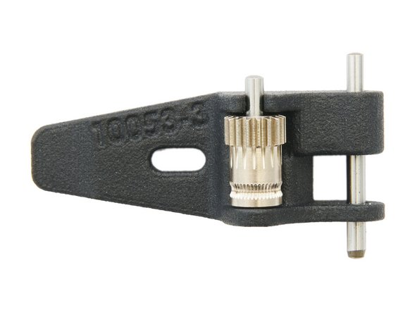
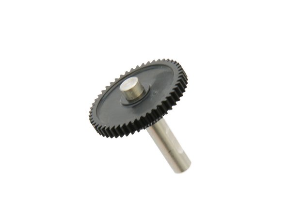
Align the gear (with the shaft) in the hinge as shown in Fig. 2 and press the shaft down until it engages.
-
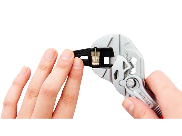
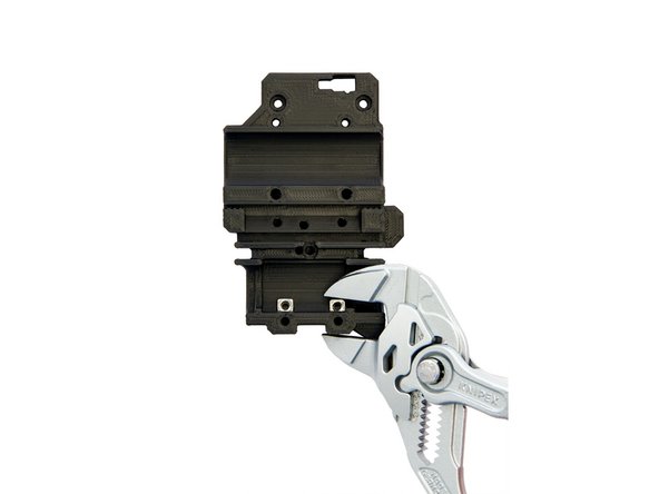
Carefully press the shaft into position with a pliers wrench.
-
Re-assemble the hinge with the shaft to the back of the extruder.
-
-
-
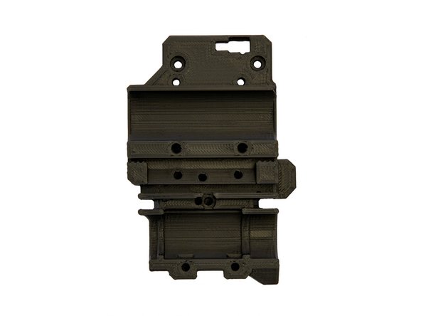
Remove the shaft assembly from the front of the extruder.
-
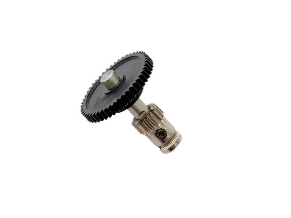
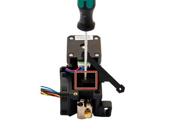
Slide the gear onto the shaft and make sure that the M2 grub screw is aligned with the flat side of the shaft.
-
Tighten the screw so that the gear can only move up and down.
-
Insert the shaft assembly into the back of the extruder next to the hinge.
-
Make sure that there is a ball bearing (5x8x.2.5) in the cavity for the shaft.
-
Align the grooves in the gear to match the filament path and tighten the M2 grub screw.
-
-
-
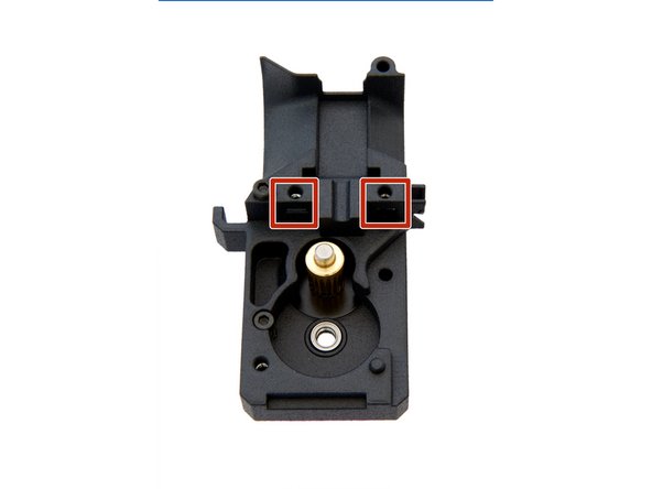
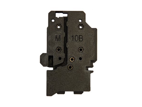
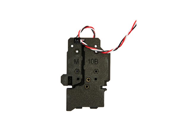
Insert a M3 Square Nut into the hole, in the center of the extruder back. Make sure that the square nut is inside the left slot.
-
Remove shaft assembly from the back of the extruder and insert into the front of the extruder.
-
Make sure that there is a ball bearing (5x8x.2.5) in the cavity for the shaft.
-
-
-
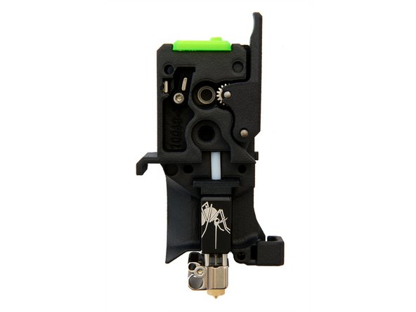
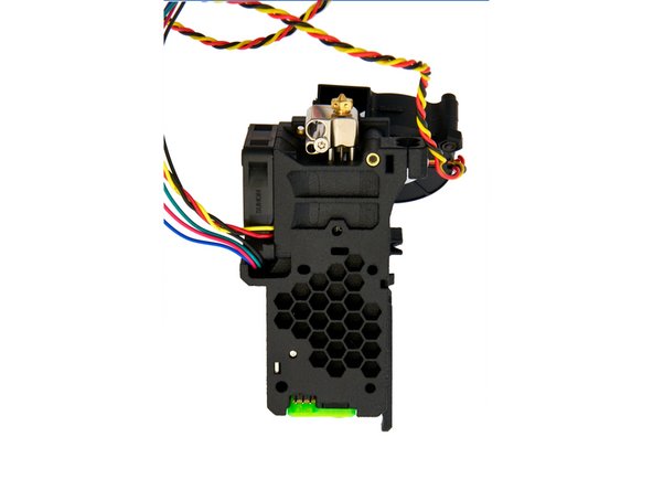
Place your Mosquito/ Mosquito Magnum Hotend built in Manual 14.1. into the back of your extruder.
-
Make sure all components are seated properly before proceeding.
-
-
-
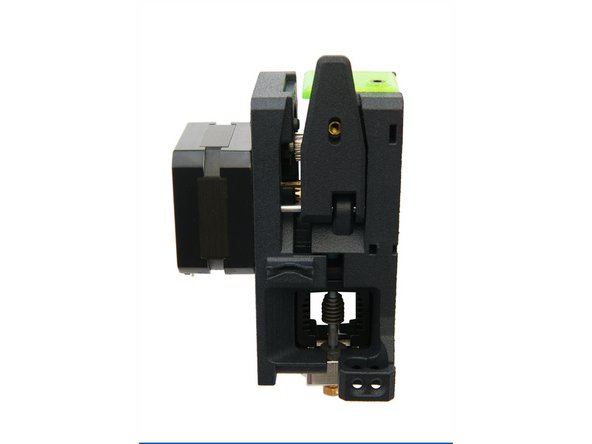
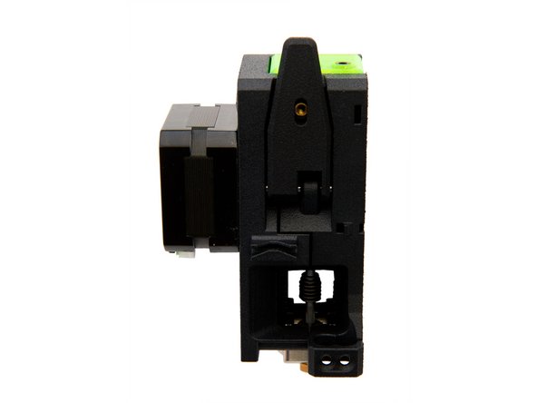
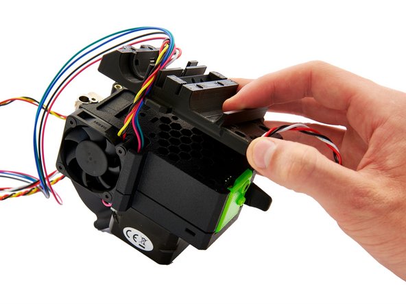
Now, put the front and back of the extruder together.
-
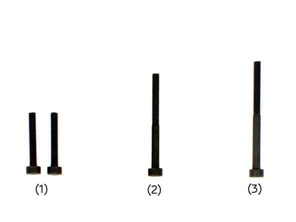
At the bottom of the front of the extruder, screw a M3x35mm Hexagon Socket Head Cap Screw through the extruder.
-
-
-
At the bottom of the front of the extruder, screw a M3x35mm Hexagon Socket Head Cap Screw through the extruder.
-
-
-
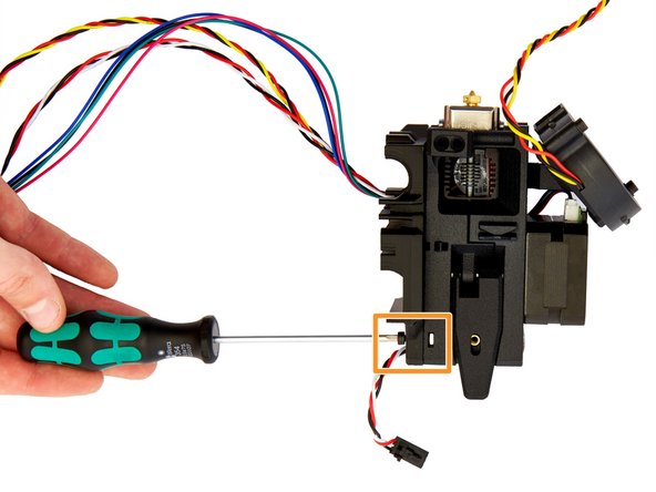
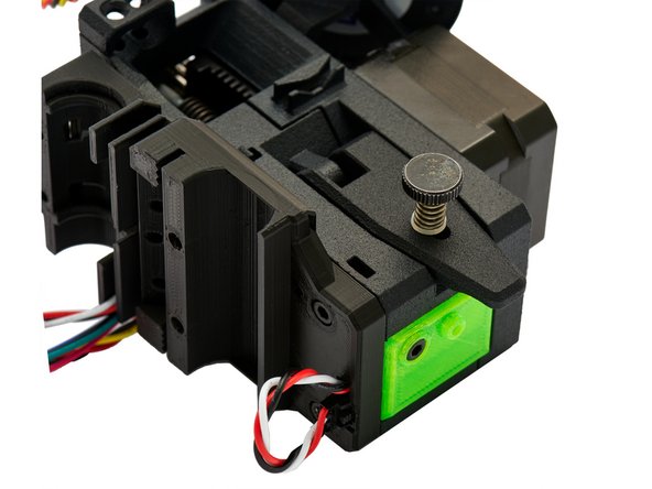
Install the Thumbscrew. Tighten the thumbscrew as much as possible and then loosen it again by 2-3 turns.
-
Insert a M3 Square Nut at the bottom of the back of the extruder.
-
Insert a M3 Square Nut into the top left corner of the back of the extruder.
-
-
-
On the Sunon Fan, enlarge the four screw holes with a countersink and remove the cable guide.
-
Plug the motor cable into the motor on the front of the extruder.
-
Push the motor cables into the cavity.
-
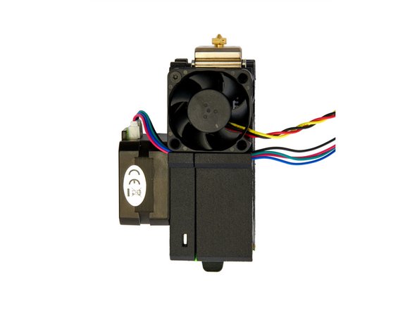
Place the Sunon Fan over it and be carefull to not damage the cables.
-
Pay attention to the orientation of the fan. The sticker on the fan must face inwards and the cable must come out to the rear.
-
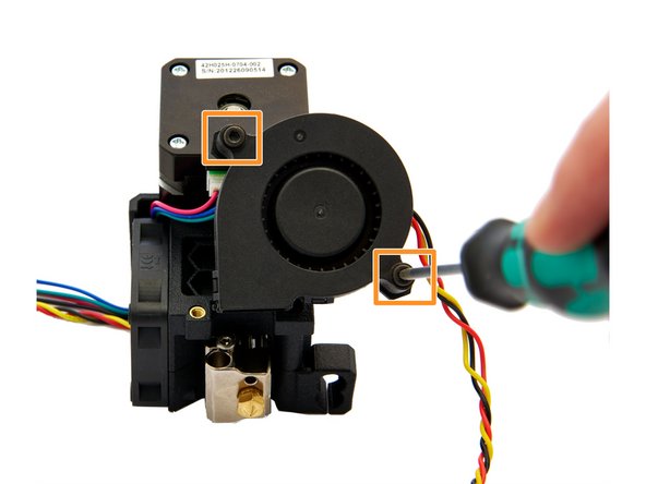
Attach the Sunon Fan to the extruder using 4x M3x16mm Flat Head Screws.
-
-
-
Insert 2x M3 Nuts into the fan holder.
-
Attach the fan holder to the extruder with a M3x10mm Hexagon Socket Head Cap Screw.
-
Carefully attach the Radial Fan to the extruder, using 2x Black Washers and 2x M3x20mm Hexagon Socket Head Cap Screws.
-
-
-
Insert 2x M3 Square Nuts into the bottom of the front of the x-carriage.
-
-
-
Feed the filament sensor cable connector through the top slot in the x-carriage (Fig. 1).
-
Pull the cable all the way through and insert the filament sensor cable connector (as shown in Figure 3) into the slot until it engages.
-
-
-
Now, feed the filament sensor cable through the cable guide in the back of the x-carriage.
-
Finally, remove the filament sensor cable connector from the x-carriage to avoid damaging the filament sensor during the installation of the x-carriage.
-
-
-
Place the x-carriage on the back of the extruder.
-
Be careful not to damage the filament sensor cable.
-
-
-
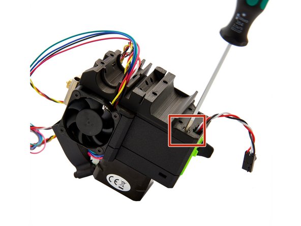
At the top right, the x-carriage is fastened with a M3x40mm Hexagon Socket Head Cap Screw.
-
At the top left, the x-carriage is fastened with a M3x10mm Hexagon Socket Head Cap Screw.
-
Plug the filament sensor cable onto the sensor.
-
Make sure that the plug snaps into place.
-
-
-
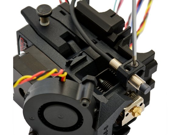
Insert the pinda into its mounts and fasten it with a M3x16mm Flat Head-Head Socket Cap Screw at the level of the nozzle.
-
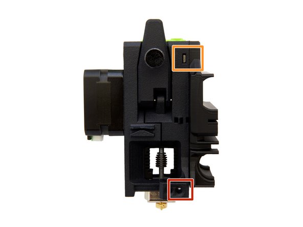
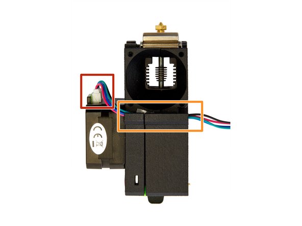
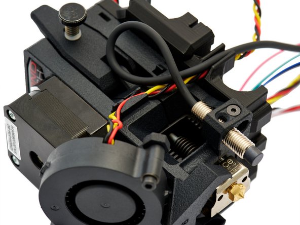
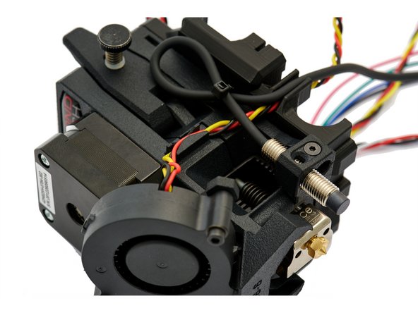
Plug the cable of the radial fan into the mount provided on the right side of the extruder and guide it to the x-carriage.
-
Run the cable along the extruder (as shown in Fig. 3) and secure it with a zip tie.
-
-
-
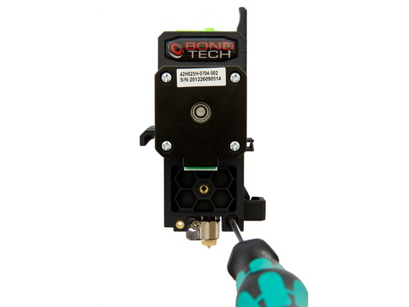
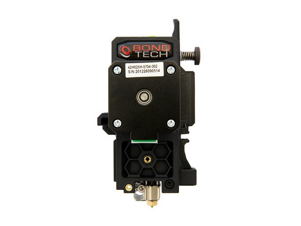
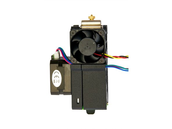
The assembly of the Extruder is completed now.
-
Continue with instructions 16.1 Installation and Wiring of the Bondtech MK3S Mosquito Extruder.
-