-
-
(1) Heater Cartridge
-
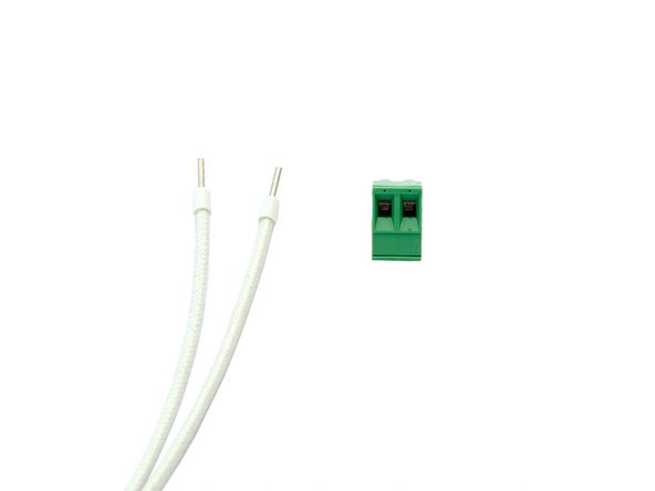
(2) Thermistor Extension Cable
-
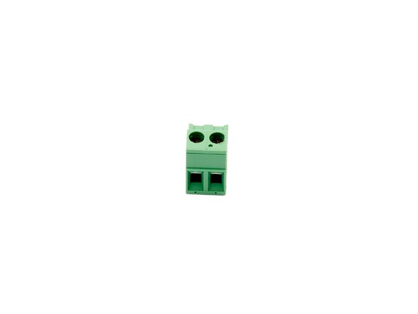
(3) Terminal Block
-
(4) Zip Ties
-
If you are building a Caribou 320 or 420 you will need the following extension cables:
-
-
(6) 2x Fan Extension Cable
-
(7) 2x Motor Extension Cable 20cm
-
-
-
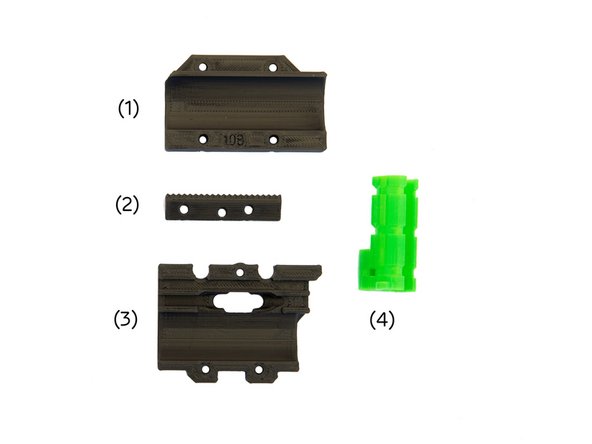
(1) x-Carriage Back (Top)
-
(2) Belt Holder
-
(3) x-Carriage Back (Bottom)
-
(4) x-Cable Holder
-
-
-
-
Caribou 220: 45cm
-
Caribou 320: 55cm
-
Caribou 420: 65cm
-
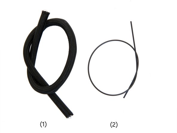
(2) Nylonfilament
-
Caribou 220: 47cm
-
Caribou 320: 57cm
-
Caribou 420: 67cm
-
-
-
-
-
-
-
-
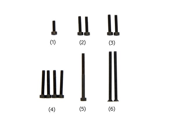
(6) 2x M3x45mm Hexagon Socket Head Cap Torx Screws
-
-
-
Turn your 3D printer around.
-
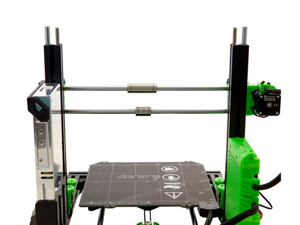
Move the x-axis to the upper third of the z-axis and push the two bushings on the x-axis to its center.
-
Check whether the two square nuts are located in the lower part (insertion for the lower bushing) of the x-carriage.
-
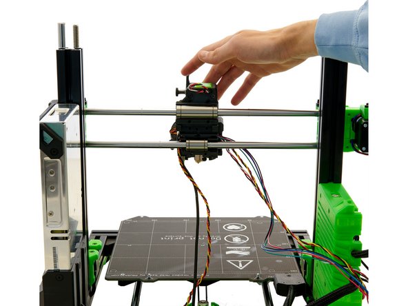
Hold the extruder against the bushings and make sure they are positioned in their designated openings.
-
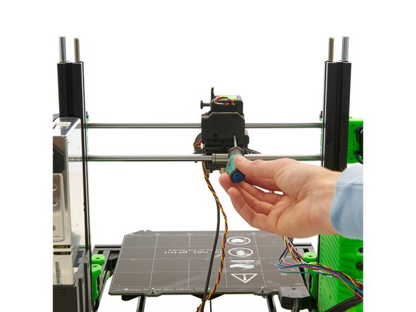
Cover the upper bushing with the back of the x-carriage. Then, fasten the x-carriage back to the extruder with 4x M3x22mm Hexagon Socket Head Cap Screws.
-
-
-
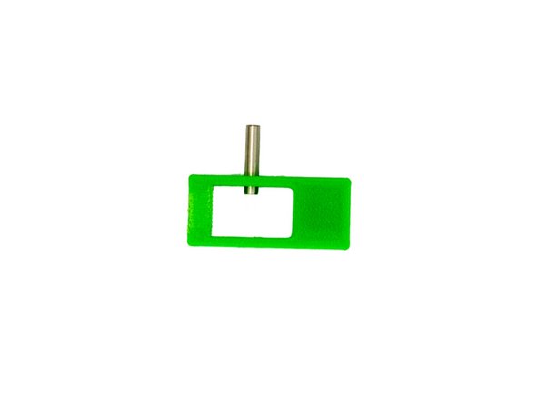
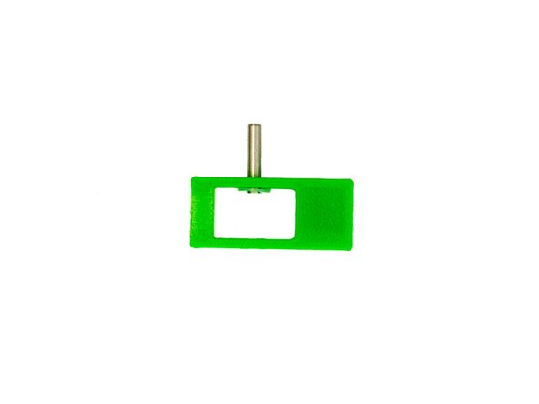
Take the xy-belt tensioner insert and enlarge one of the two holes on its side (e.g. with a 2.5x75mm hexagonal screwdriver).
-
Slide a dowel pin through the hole you just enlarged and push it in until it is just visible inside the xy-belt tensioner insert.
-
Place a M3 Plastic Washer on the dowel pin. (Fig. 2).
-
-
-
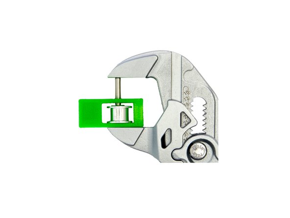
Now place a toothless pulley on the dowel pin. Continue to push the pin down until it reaches the end of the toothless pulley (Fig. 1).
-
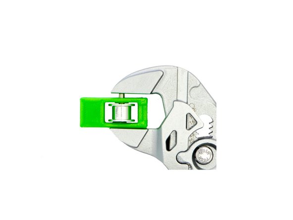
Place a M3 Plastic Washer on the toothless pulley and, with the pliers wrench, push the dowel pin as far as possible through the opening of the xy-belt tensioner insert (Fig. 2)
-
Finally, place an M3 Self-Securing Nut into the designated slot. Press the nut completely into the slot.
-
Pay attention to the orientation. The blue circlip must point towards the pulley.
-
The xy-belt tensioner insert is now fully assembled.
-
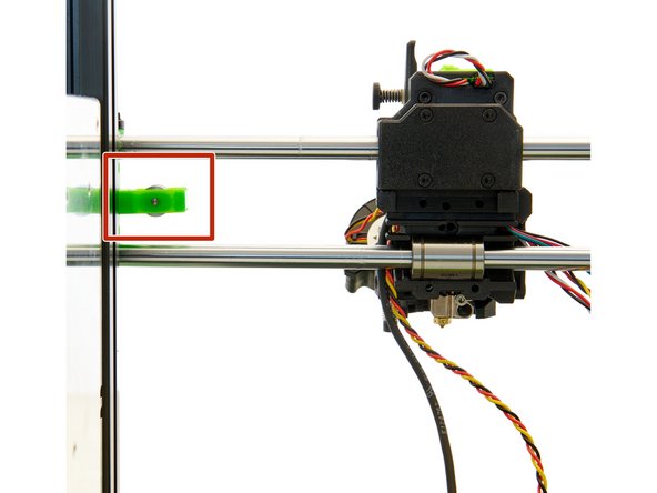
Since you will need a second xy-belt tensioner insert for the x-axis, you can build another one in this step.
-
-
-
Insert the xy-belt tensioner insert into the idler.
-
Take the second half of the GT3 belt and shorten it to the length of 82 cm.
-
Cut the remaining GT3 belt to the length of 82cm.
-
Pull the belt through the xy-belt tensioner insert (Fig. 2).
-
Push the end of the belt to approximately the center of the mount provided for it in the x-carriage.
-
-
-
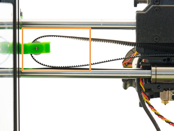
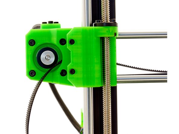
Place the GT3 belt around the GT3 toothed pulley on the stepper motor at the x-motor holder.
-
Slide the xy-belt tensioner insert into the y-Idler.
-
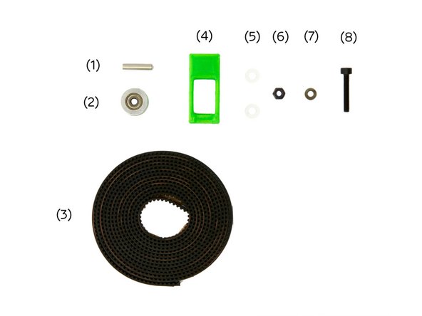
Secure the xy-belt tensioner insert with an M3 Washer and an M3x18mm Hexagon Socket Head Cap Screw.
-
Make sure the strap holder is flush with the idler for this step.
-
-
-
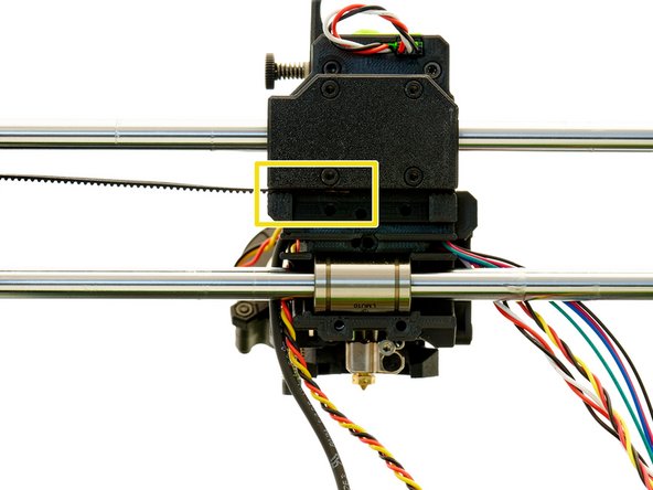
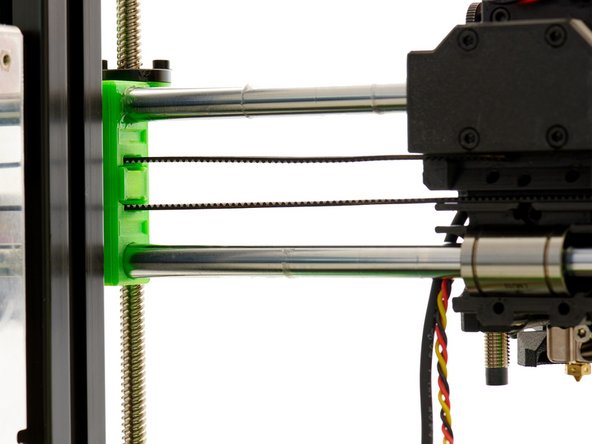
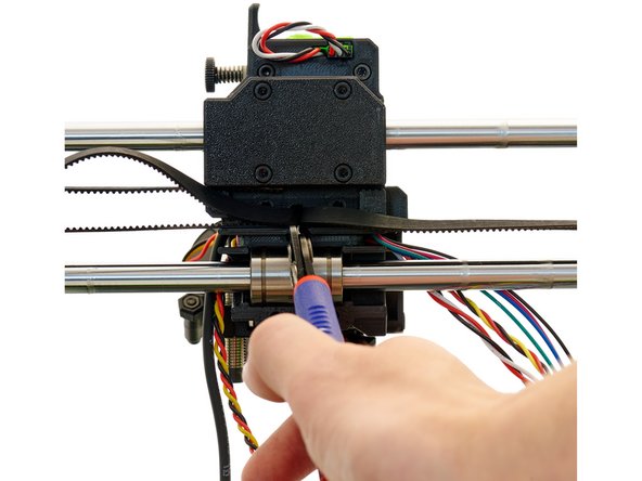
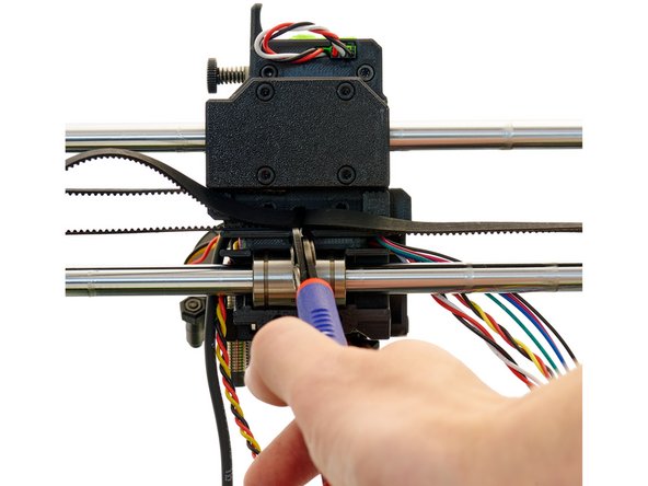
Now, guide the belt back to the x-carriage. If the two belt ends are overlapping in the middle, cut the protruding end.
-
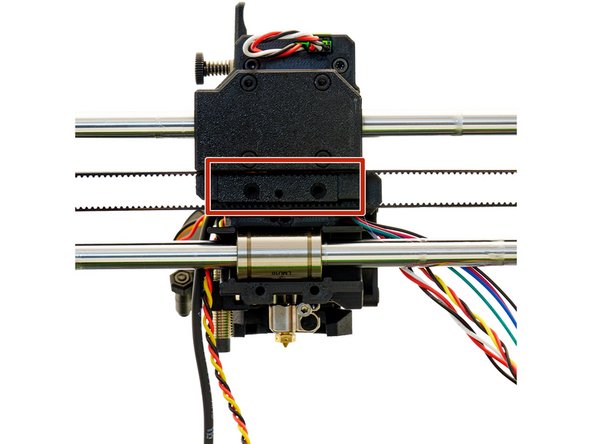
Place the belt holder in the x-carriage.
-
Fasten the belt holder with 2x M3x45mm FlatHead Screws.
-
-
-
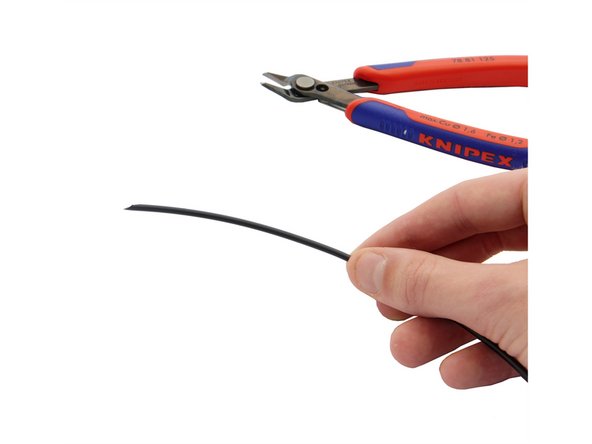
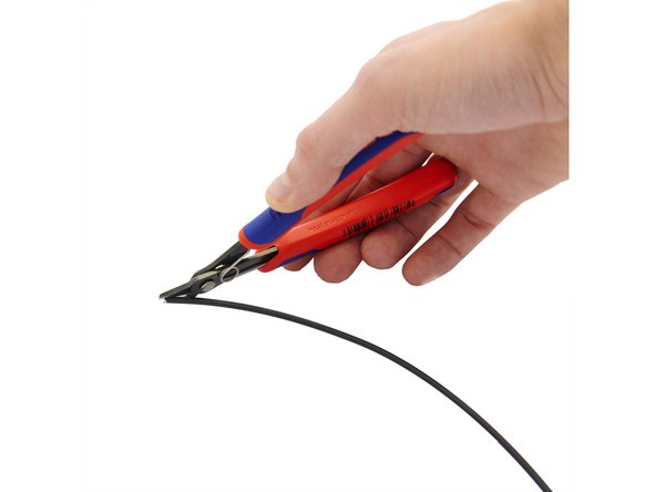
Cut your nylon filament so that the length fits your printer model (see Step 5).
-
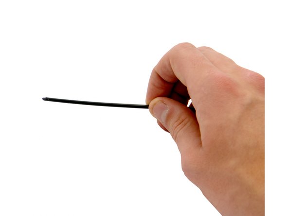
Now, cut a slanted edge from one of the ends to make it pointed.
-
-
-
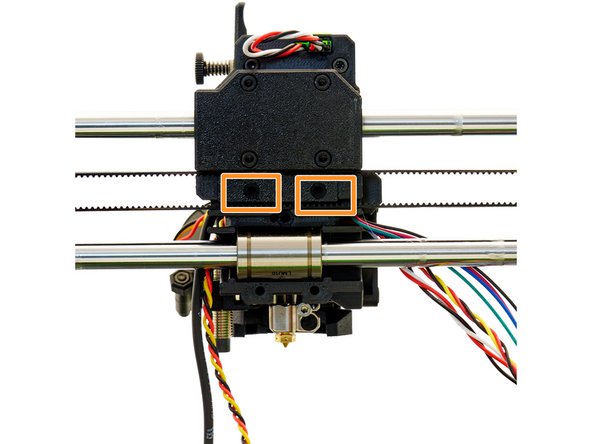
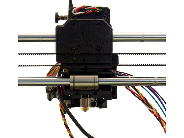
Insert the pointed end of the nylon filament into the left hole in the center of the x-carriage.
-
Use a M3x10mm Hexagon Socket Head Cap Screw in the right hole in the center of the x-carriage to attach the nylon filament.
-
-
-
After that, pass the pinda cable, the filament sensor cable, the motor cable, the two fan cables and finally the nylon through the hole in the center of the x-carriage back (bottom).
-
Attach the x-carriage back (bottom) using 2x M3x16mm Hexagon Socket Head Cap Screws.
-
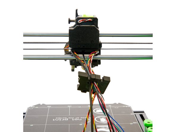
Fasten the x-cable holder to the extruder with a M3x40mm Hexagon Socket Head Cap Screw.
-
-
-
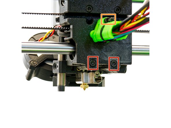
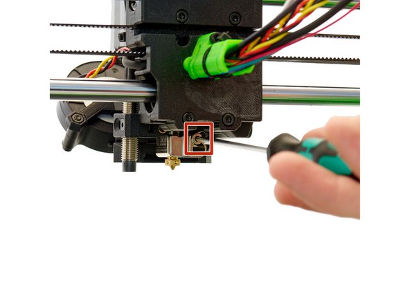
Loosen the M2x5mm Hexagon Socket Head Cap Screwon the Slice Engineering Hotend.
-
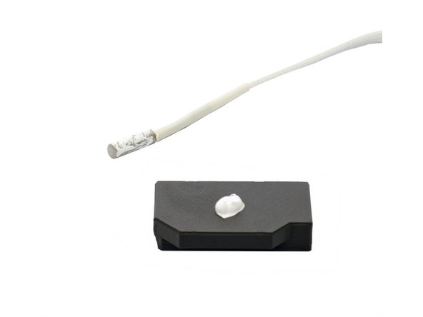
Open the boron nitride paste and apply it to the heater cartridge and the thermistor cartridge.
-
Insert the heater cartridge into the lower opening and the thermistor into the upper opening in the hotend. Secure both with a (previously removed) M2x5mm Hexagon Socket Head Cap Screw.
-
-
-
Cut Techflex tube and nylon to fit your printer model (see Step 5).
-
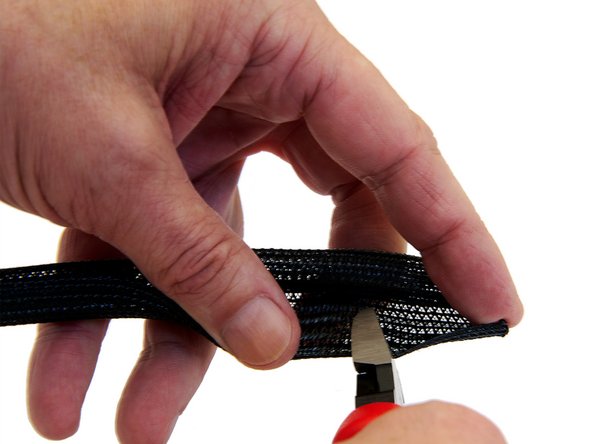
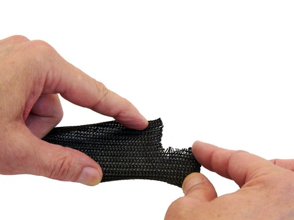
Cut an approximately 3x2cm rectangle from on one side of the Techflex tube (about 5cm before the end of the tube).
-
-
-
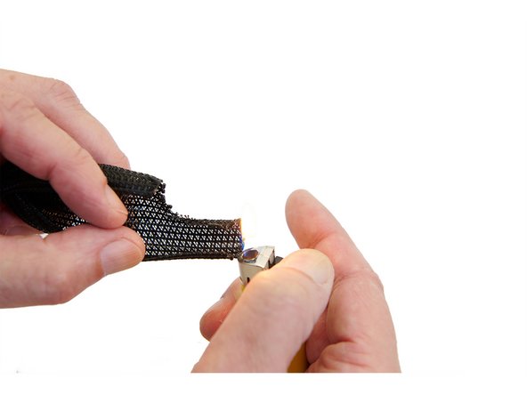
The two ends of the Techflex tube are then briefly heated with a lighter.
-
-
-
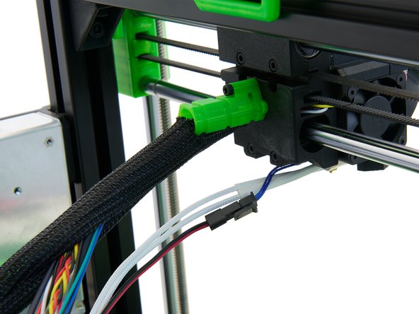
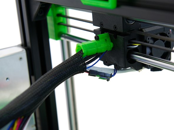
Push all the cables and the nylon filament through the Techflex tube you just prepared. Here, the end of the tube with the cut-out rectangle must be directed at the extruder.
-
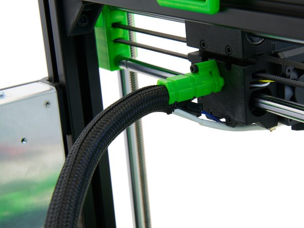
Slide the Techflex tube completely into the x-cable holder and align the rectangle with the bottom to position the heater cartridge and thermistor cartridge cables there.
-
-
-
Now, route the heater cable and thethermistor cable through the rectangle and into the Techflex tube.
-
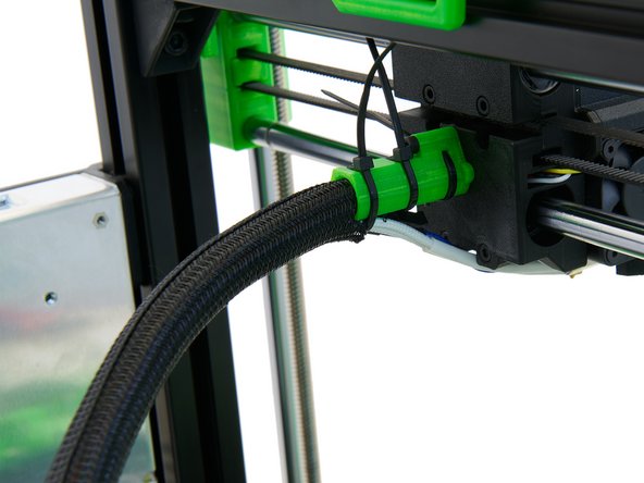
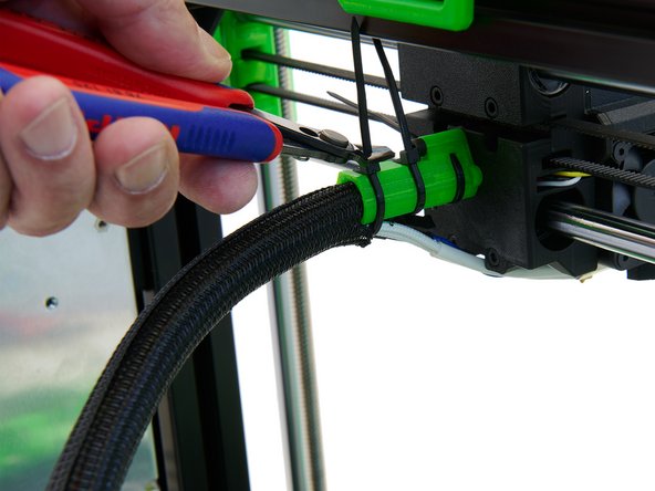
Secure the cables in the x-cable holder with 3x Zip Ties.
-
-
-
If you are building a Caribou 320 or Caribou 420, you will need to extend the pinda cable and extruder motor cable with a motor extension cable, the filament sensor cable with a filament sensor extension cable, and both fan cables with a fan extension cable.
-
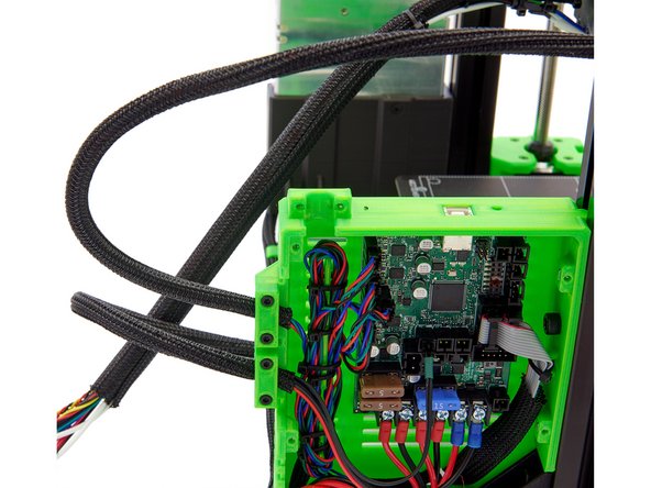
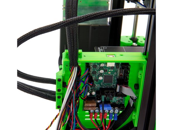
Attach the Techflex tube to the Einsy box using the cable holder (straight) and 2x M3x14mmm Hexagon Socket Head Cap Screws.
-
-
-
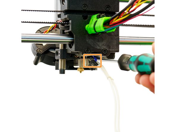
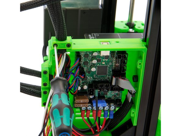
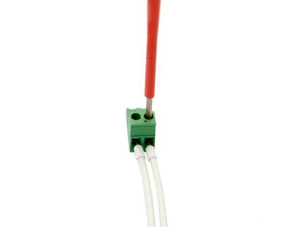
Use a screwdriver for slotted screws to loosen the two screws on the terminal block.
-
Push each of the two cable ends of the thermistor cartridge into one opening and secure them.
-
-
-
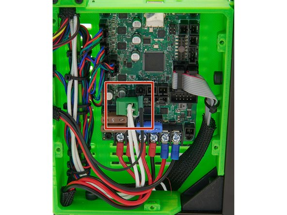
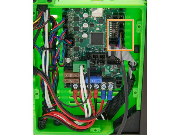
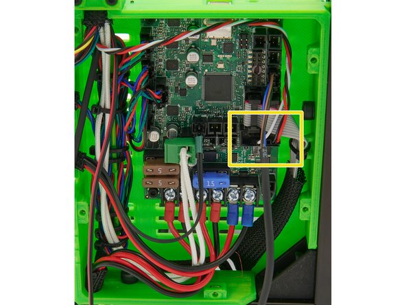
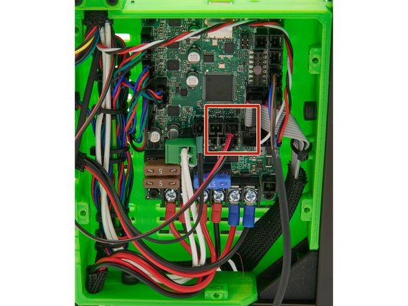
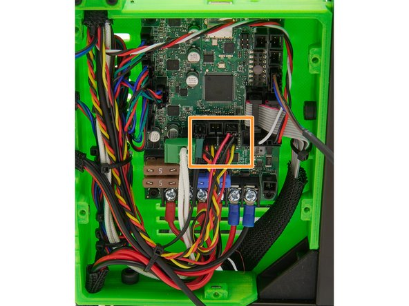
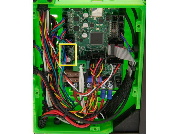
Now, connect the components to the board:
-
Heater cartridge
-
PINDA2 / SuperPINDA
-
Filament sensor (lower row of pins at the tub connector, white cable to the left)
-
-
-
Thermistor
-
Extruder-Fan (left), Radial-Fan (right)
-
Extruder-Motor
-
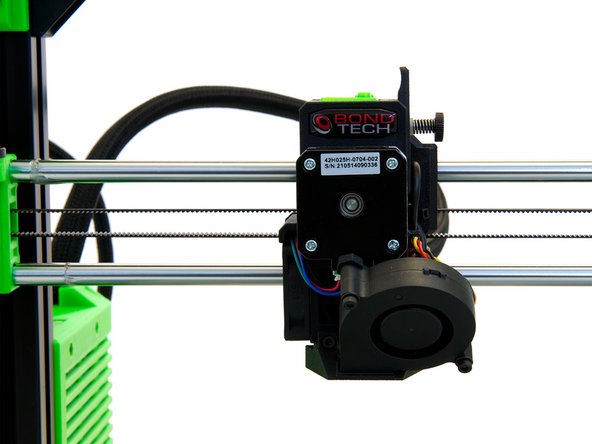
The extruder is now completely wired.
-
-
-
The installation of the extruder is completed now.
-
Continue with instructions 17. Installation of the Upper x-Profile.
-
Cancel: I did not complete this guide.
One other person completed this guide.


