-
-
(1) Computer
-
(2) PSU cable
-
(3) USB cable
-
(4) Zip Ties
-
(5) Silicone Sock (only required if the E3D Hotend is installed)
-
(6) Foil Squeegee with Alcantara Cover (only required for BuildTak)
-
(7) Isopropanol
-
-
-
-
-
-
(4) Torque Wrench 1,5Nm (only required if a vanadium nozzle is installed)
-
Alternatively, a 6mm Cross-Handle Socket Wrench can be used.
-
(5) Pliers Wrench (only required for E3D Hotend)
-
Alternatively, you can use a...
-
(6) 16mm Open-End Wrench
-
-
-
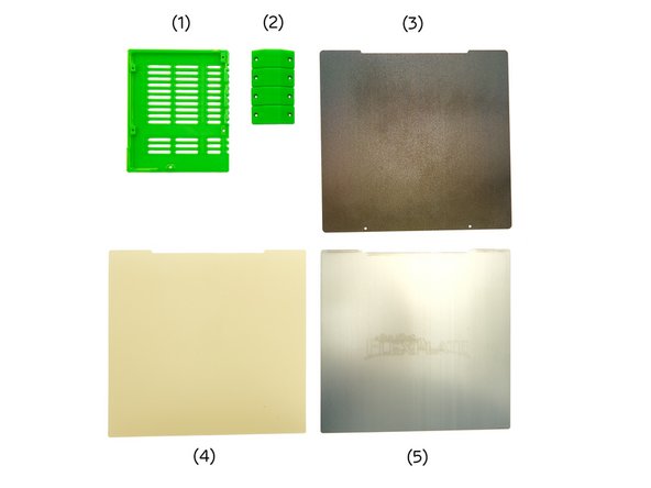
(1) Einsy Box Cover
-
(2) 4x Rod Holder Cover
-
Printing Surface
-
-
or
-
-
and
-
-
-
-
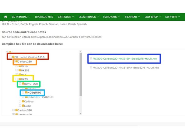
Visit Caribou3d.com to select the matching firmware for your printer model:
-
In the file manager, first select the folder "01_LatestVersion x.x.x".
-
Now, select your printer model and download the appropriate firmware. In our example we select a German firmware for a Caribou 220 MK3S with a Bondtech Mosquito and an SL Thermistor.
-
Printer height
-
Printer model
-
Extruder
-
Hotend
-
Finally, you have to choose a language ("EN" or "MULTI") and a thermistor version ("BM" or "BMH").
-
-
-
Download the program "Prusa Slicer" to your computer and install it on your PC / laptop.
-
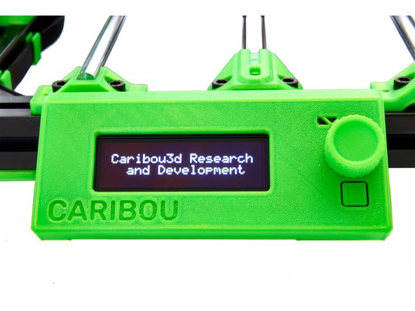
Connect the power cable to the printer and turn it on.
-
The display should show the words "Caribou Research and Development" and the two fans should be activated.
-
Connect your printer to your computer using the supplied USB cable.
-
-
-
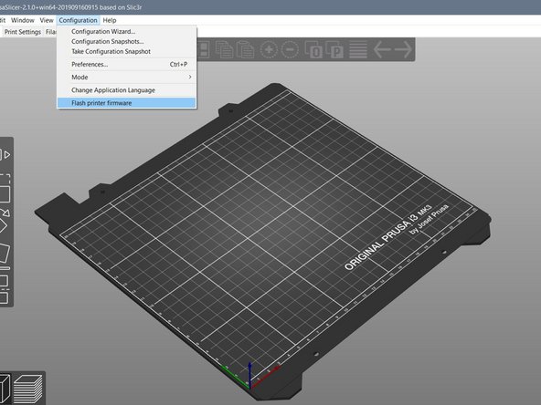
Open Prusa Slicer.
-
Select the following buttons in the top bar:
-
Configuration
-
Flash Printer Firmware
-
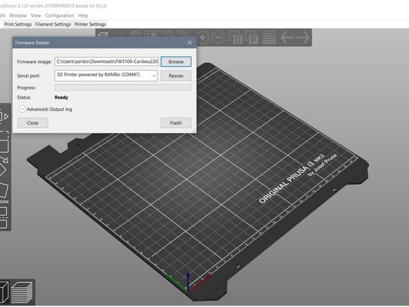
For Serial Port select "3D Printer powered by RAMBo".
-
At Firmware image select the firmware you downloaded.
-
Lastly, select "Flash".
-
This process may take a few minutes.
-
-
-
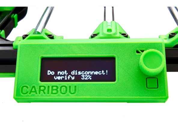
In the first step, the firmware is written.
-
In the second step, it is verified.
-
Do not interrupt this process! Damage to the Einsy board may occur.
-
-
-
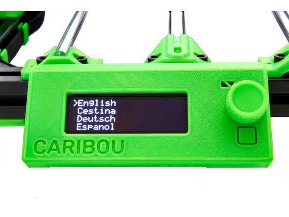
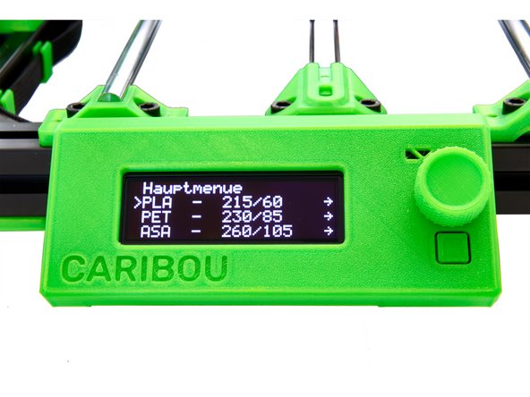
Once the firmware upgrade is complete, you can select your preferred language for multi-language firmware.
-
Turn the knob on the display to switch between entries and press once to select individual entries.
-
Press the lower button to restart your printer.
-
You will then be asked if you want to use the "Wizard". Select "no" here.
-
-
-
You will then be asked if you want to use the "Wizard".
-
Select "no" here.
-
A message to restart the wizard will be displayed.
-
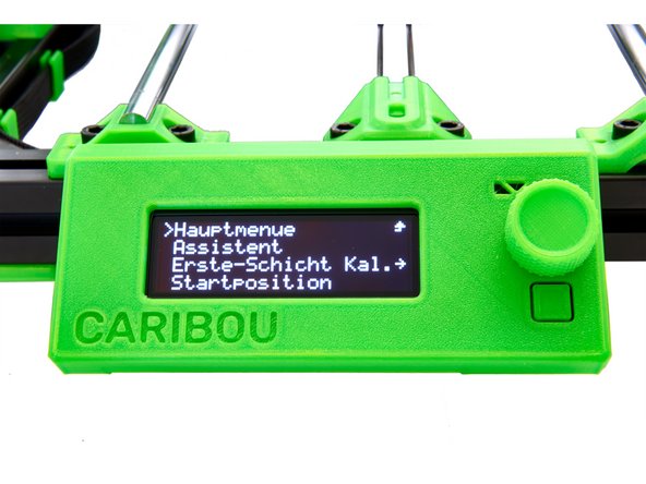
After pressing the knurled knob again, the selection menu is displayed.
-
-
-
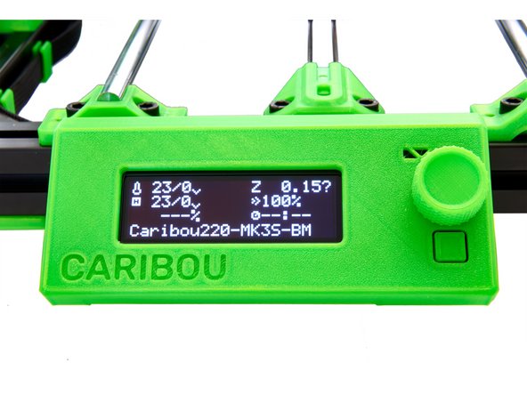
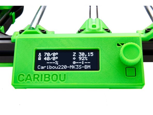
After pressing the knob again, you will see the start screen.
-
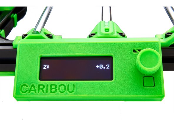
Press and hold the knurled knob for 2-3 seconds. The display should now show "Z: +0.2".
-
Turn the knurled know clockwise. This will cause the x-axis to move upwards.
-
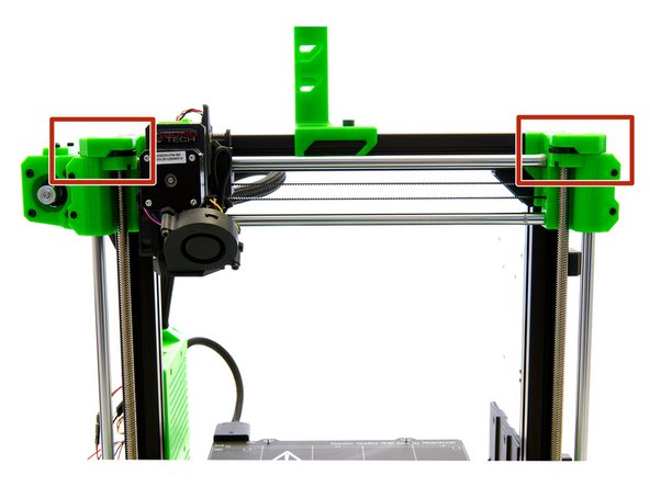
Move the x-axis all the way up against the top mounts to make sure the x-axis is parallel to the bed.
-
This will produce a loud noise, which is normal.
-
Check whether both sides are touching the top mounts. If this is not the case, check to see why there is a blockage.
-
By turning the knob counterclockwise, you now move the axis down 3-4cm.
-
Press the knurled knob once to display the start screen.
-
-
-
Before proceeding, make sure the pinda is level with or slightly lower than the nozzle.
-
Press the knob again to go to the main menu.
-
There you select the following buttons:
-
Calibration
-
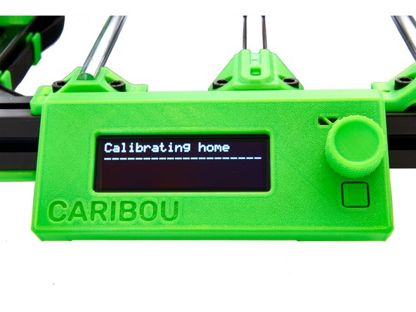
Autohome
-
The printer now moves each of the three axes to neutral position and then moves to the first reference point on the heatbed.
-
The start position is on the front left of the heatbed.
-
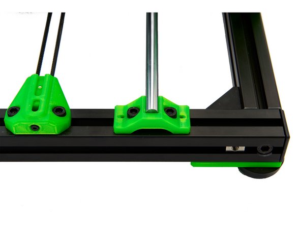
If the printer moves to a rear left position, you probably mounted the beltholder and the y-slide in the wrong direction and have to rotate it.
-
-
-
Press the knob again to go to the main selection.
-
There you select the following buttons:
-
Calibration
-
Selftest
-
Before proceeding, make sure the pinda is level with or slightly lower than the nozzle.
-
-
-
The firmware first verifies that both fans are spinning and connected properly.
-
After the first fan is checked and running, you will be asked whether the extruder fan (fan on the left side) is spinning. Check this and answer accordingly.
-
Now you are asked whether the part cooling fan (fan at the front) is spinning. Check this and answer accordingly.
-
If the test shows that the fan connections on the Einsy board have been reversed, switch off the printer and replace them. Then run the self-test again. If the test shows that the fan connections on the Einsy board have been reversed, switch off the printer and replace them. Then run the self-test again.
-
-
-
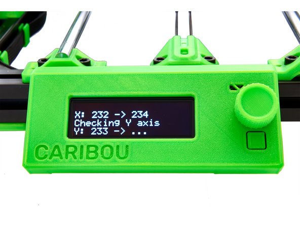
The firmware now checks whether the length of the three axes is correct.
-
First, the length of the x-axis and the y-axis is measured.
-
If an error message appears, check if there are cables sticking out from the sides of the extruder which are blocking the axis. For the y-axis, check the installation of the bearing holders and the installation of the belt holder or pulley.
-
If the SuperPINDA / PINDA does not activate properly, check the cables.
-
The start position is then calibrated.
-
The last part of the self-test is to check the heating of the heatbed and extruder.
-
If an error occurs here, check the wiring.
-
This completes the self-test successfully.
-
-
-
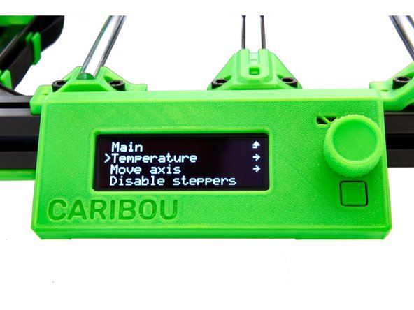
Select the following buttons in the main menu under Settings:
-
Temperature
-
Nozzle
-
Set the temperature to 250°C. Press the control knob twice to return to the start screen.
-
On the start screen you can monitor the temperature rise.
-
-
-
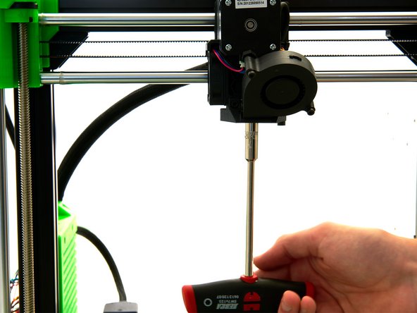
If you have installed a Mosquito Hotend, tighten the nozzle carefully with a t-handle socket wrench.
-
If you have installed a Mosquito Hotend with a Vanadium Nozzle, tighten the nozzle with a torque wrench.
-
If you have installed an E3D Hotend, hold the heater block with a 16mm open-end wrench and carefully tighten the nozzle with a t-handle socket wrench.
-
Make sure that the heating block is aligned straight.
-
-
-
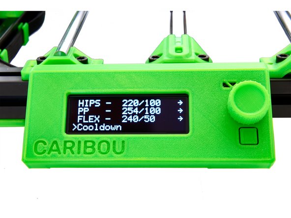
Select the following buttons in the main selection under Settings:
-
Preheat
-
Cooldown
-
Wait until the temperature has dropped below 50°C.
-
If you have installed an E3D Hotend , you can insert the silicone sock.
-
Make sure that it is not sitting above the cables, but below them.
-
-
-
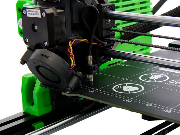
Move the x-axis all the way down and turn off the printer.
-
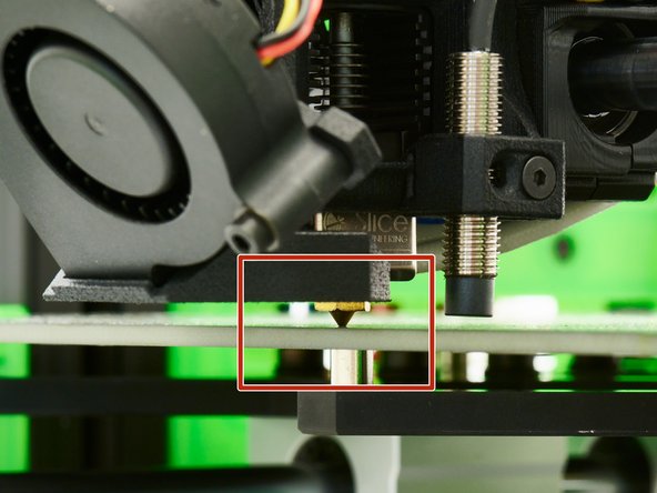
Turn the two spindles of the z-stepper motors simultaneously and evenly downward until the nozzle touches the bed.
-
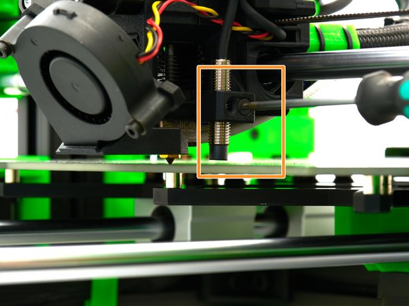
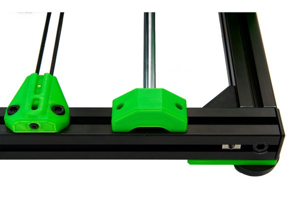
Loosen the M3x16mm Flat Head-Head Socket Cap Screw that holds the pinda in place.
-
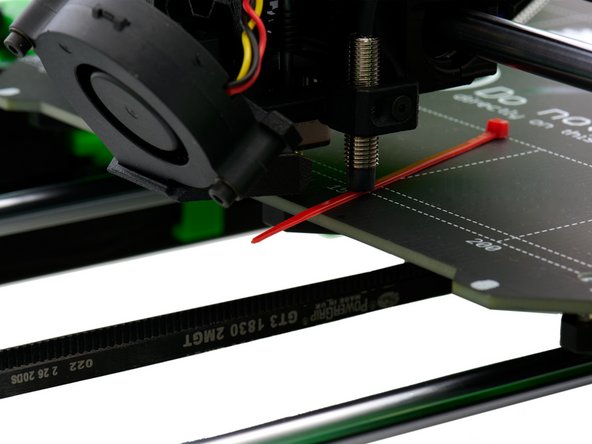
For illustration purposes, the zip tie in Fig. 3 is colored red.
-
Slide a zip tie beneath the PINDA and re-tighten the M3x16mm Flat Head-Head Socket Cap Screw.
-
The distance between the PINDA and the bed is now approximately 0.6mm. For a SuperPINDA, take a credit card or something similar. The distance should be about 1mm.
-
Turn the printer back on and realign the x-axis (see Step 11).
-
-
-
Press the knurled knob again to get to the main selection.
-
There, select the following buttons:
-
Calibration
-
Belt Test
-
Now the tension of the x- and y-belts is measured. The value should be between 225 and 250. A smaller value means higher tension.
-
If necessary, adjust the tension of the belts by loosening or tightening the set screw on the front belt holder and on the side of the middle screw on the x-Idler. After a readjustment, you must repeat the test.
-
-
-
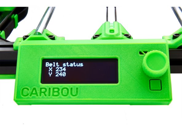
You can check the current value of the belt tension as follows:
-
Press the knurled knob again to get to the main selection.
-
There, select the following buttons:
-
Support
-
Belt Status
-
Only the value of the last measurement is displayed. If an adjustment has been made, the belt test must be performed again.
-
-
-
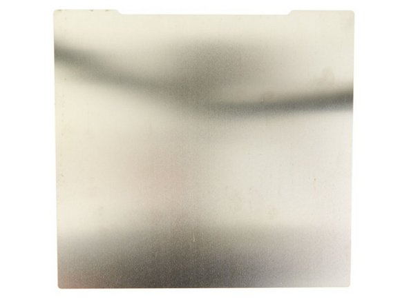
Remove the sticker from the BuildTak steel sheet and clean the sheet with isopropanol.
-
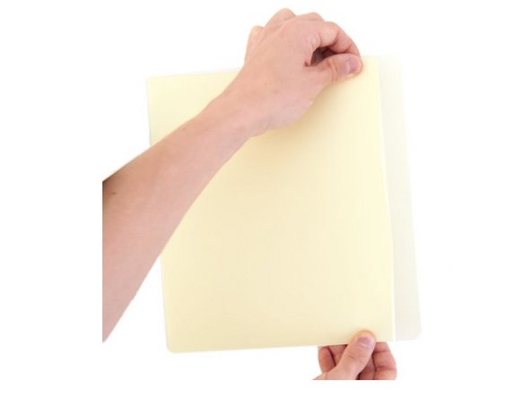
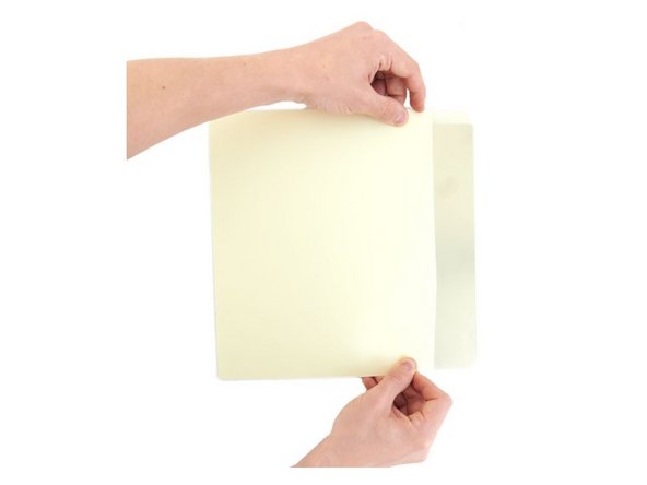
Remove the protective foil from the MK52 PEI Sheet by approx. 2-3cm.
-
Stick the MK52 PEI on the BuildTak Sheet side without logo.
-
Align the MK52 PEI Sheet on the BuildTak steel sheet (see Figure 3).
-
-
-
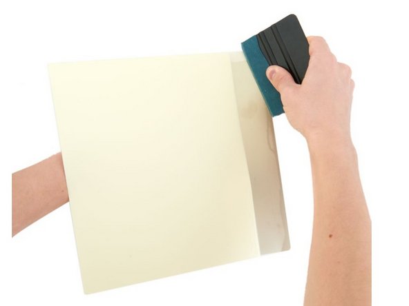
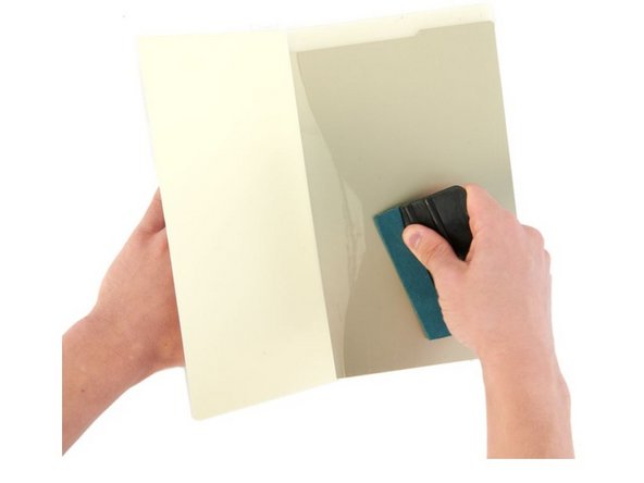
Now use the foil squeegee (or a spatula with a microfiber cloth) to apply the MK52 PEI Sheet to the Flexible Steel Sheet.
-
Remove the protective film piece by piece and squeegee the MK52 PEI Sheet to the Flexible Steel Sheet.
-
Always work in the direction of the not yet adhered MK52 PEI Sheet or towards the outer edges of the sheet.
-
Be especially careful around the edges. Only squeegee outwards. Otherwise, there is a risk that you will lift the MK52 PEI Sheet.
-
If necessary, remove the protruding parts of the MK52 PEI Sheet carefully with e.g. a knife.
-
Finally, clean the surface with isopropanol.
-
-
-
Select the following buttons in the main selection:
-
Calibration
-
Calibration XYZ
-
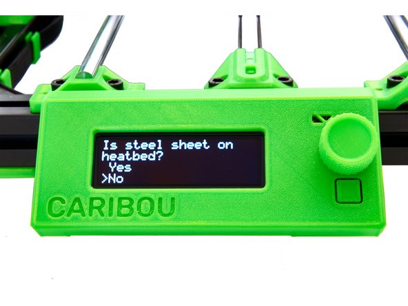
Make sure that there is no printing sheet on the heating bed. If the printer asks you about this, select "No".
-
Be careful that the Nozzle does not scratch the heatbed while the printer is measuring the 4 dots in the heated bed.
-
After measuring, the x-axis is moved up slightly. Now place your printing sheet on the heatbed to continue with the calibration.
-
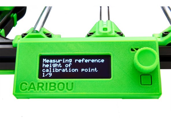
The printer then measures 9 points on the bed.
-
-
-
The position of the four calibration points is measured.
-
After measuring, the x-axis is moved up slightly. Now, place your printing sheet on the heatbed to proceed with the calibration.
-
Now, the height of nine points on the printing bed is measured.
-
As the last step, the result of the calibration is displayed.
-
If the bed is crooked or if there is a fault, check the installation of the heatbed and the carriage.
-
-
-
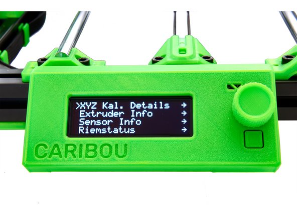
The details of the calibration can be viewed under the support menu.
-
Select the following buttons in the main selection:
-
Support
-
XYZ Cal. Details
-
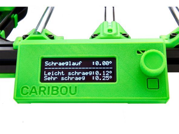
The most important factor here is the skew (the smaller, the better). If the value is below 0.11°, the printer will not perform any adjustments.
-
-
-
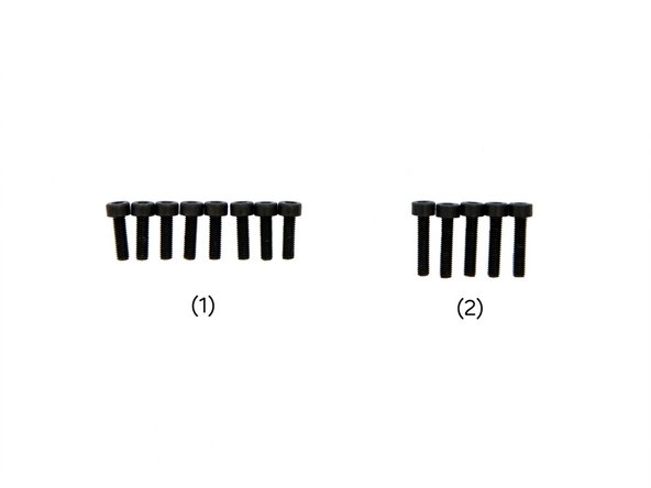
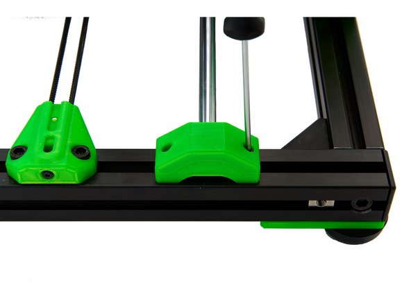
Place the rodholder covers (top) on the rodholders (bottom).
-
Now, tighten them with 2x M3x10mm Hexagon Socket Head Cap Screws.
-
Be careful not to overtighten the screws or the nuts underneath the rodholders may fall out.
-
-
-
Select the following buttons in the main selection under Settings:
-
Preheat
-
PLA
-
On the start screen you can monitor the temperature rise.
-
-
-
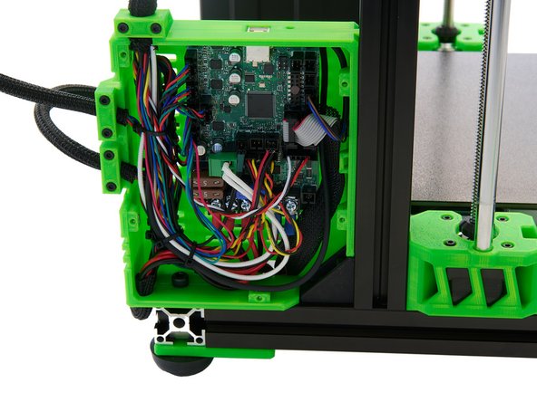
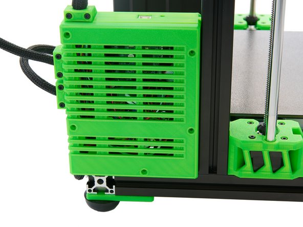
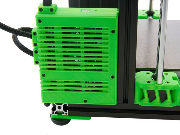
Place the cover on the Einsy Box.
-
Make sure that no cables are trapped between the cover and the box.
-
Now, fasten the cover with 5x M3x14mm Hexagon Socket Head Cap Screws.
-